We have a 10kW inverter which is used to control a PMSM inverter and need some help to design a better inrush current limiter during startup.
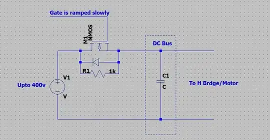
The general approach would be to let the DC bus charge safely and slowly via a series resistor, and then bypass the resistor using a relay or a contactor.
In our application we are not allowed to use any mechanical parts like relay or contactors, so a MOSFET does the job of a contactor in this case.
Here is a rough circuit of the inrush controller.

The above setup works fine, but sometimes the MOSFET gets damaged. There is no heating or any physical damage, the drain and the source of the MOSFET are always shorted (We confirmed this by physically taking the damaged MOSFET out of circuit and checking its continuity).
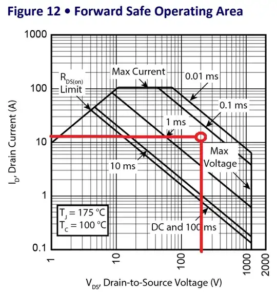
Most probably is is some SOA region failure but don't understand why, as all the parameters are within its limits.
The gate of the MOSFET is ramped up using an off the shelf Inrush controller (LTM9100).
We tried the following two cases.
We Have not connected the series resistor (R1) and completely rely on the inrush controllers ability to ramp the gate slowly. We observed that in this case a few times the MOSFET fails.
We then connect the series resistor R1, But even in this case we have observed the MOSFET failure, though the failure rate has reduced, but not completely gone. In this condition the potential at the drain and source are the same and the MOSFET should not fail, but it still does.
One more point, The MOSFET used is a switching MOSFET, and not a linear MOSFET. I understand that if the gate is ramped slowly, the MOSFET is more or less working in the linear region. But the reason we have opted for a switching MOSFET is that there are no linear MOSFETs that can withstand the high current requirement that we need.
We tried multiple MOSFETs but they all were damaged in the same way (STY145N65M5, MSC025SMA120B4).
Anyway to determine a possible root cause?
Is there a better way to limit the Inrush current in our case?
