12

I know how to detect when resistors are arranged in parallel or series arrangement and
I can also find their equivalent resistance in simple circuits or when resistances are connected in form of
triangle but what happens when the arrangement is complex like this :
Resistors

Which resistors are parallel and which are in series ? How can I find the equivalent resistance in such cases ? Is there rule or method for figuring this out ?

A Googler
  • 421

7 Answers7

27

Alfred got in before me, but I have a diagram!

I've marked all continuous bits of wire in the same colour, and marked the corresponding colours on the ends of the resistors. A quick redraw later and I get:

Resistors

which is a lot simpler!

John Rennie
  • 367,598
12

Ok, the answers given so far are pretty good and I would always choose a graphical approach, but my experience tells my that some people have difficulties morphing graphs in their heads so here is a more formal way of doing it.

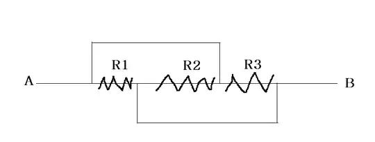
Close the circuit at points $A$ and $B$ with a voltage supply. You can identify three closed loops and apply Kirchhoff's second rule as indicated in my picture: enter image description here

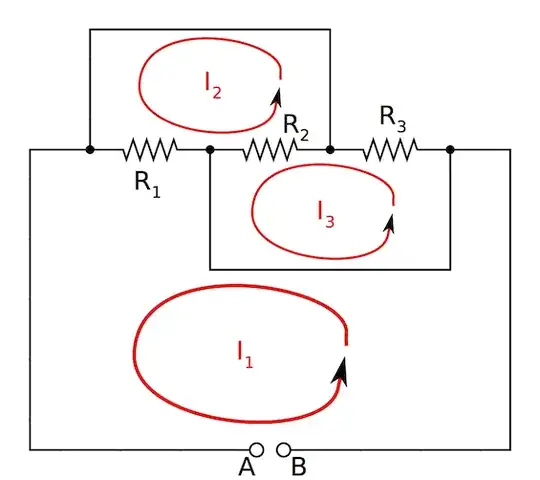
Assuming a voltage drop of $V$ between points A and B, we get:

$V = (I_1-I_2)R_1$

$0 = (I_2-I_1)R_1+(I_2-I_3)R_2$

$0 = I_3R_3+(I_3-I_2)R_2$

Now we want to replace the circuit one with only one resistor, $R_{tot}$, thus we want $V=-I_1R_{tot}$. Note the minus sign. This is because we actually have a drop, not an increase in voltage. If you forget it, it's not so bad, just keep in mind that the final resistance should be positive.

Now, we can turn this into a matrix equation:

$\begin{pmatrix}R_1+R_{tot} & -R_1 & 0\\-R_1 & R_1+R_2 & -R_2\\0 & -R_2 & R_2+R_3\end{pmatrix}\begin{pmatrix}I_1\\I_2\\I_3\end{pmatrix}=\begin{pmatrix}0\\0\\0\end{pmatrix}$

For this system to have a non-trivial solution, we need to have that the determinant of the coefficient matrix vanishes. This yields the equation:

$(R_1+R_{tot})(R_1+R_2)(R_2+R_3)-R_2^2(R_1+R_{tot})-R_1^2(R_2+R_3)=0$

Which can be solved for $R_{tot}$:

$R_{tot} = \dots = \frac{1}{\frac{1}{R_1}+\frac{1}{R_2}+\frac{1}{R_3}}$

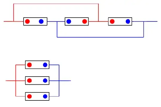
Finally, we get the same total resistance we know we would get if $R_1$, $R_2$ and $R_3$ were in parallel. Therefore, the two circuits are equivalent.

Well, I guess this post turned itself into a reminder why you shouldn't try this in an exam.

Jonas Greitemann
  • 3,979
  • 17
  • 40
9

The rule is to redraw the circuit so that it is plain to see how the circuit elements are connected.

In this case, note that one end of each resistor is connected to node A and the other end of each resistor is connected to node B so redraw the circuit that way and note that the resistors are parallel connected, i.e., the identical voltage is across all three resistors.

Even simple circuits such as this can be drawn in such a way that it isn't obvious if the circuit elements are series or parallel connected so, when it isn't clear how they are connected, try redrawing the circuit until it is.

3

Here's a visual way: If you "pull" the resistors outwards they indeed become parallel...

Animation

Shub
  • 349
1

John had already mentioned the visual way to deal with this. I thought it might be a bit more helpful if you label all the red and blue wire terminals. And simply check ✅ & connect the components one by one between the nodes

enter image description here

I hope John doesn't mind me using his diagram

0

There are many ways to solve Complex resistor circuits -- Like Parallel axis of symmetry ,

Perpendicular axis of symmetry ,

Balanced Wheat stone bridge ,

Shifted symmetry ,

Path symmetry ,KCL and KVL ,

Nodal method

Y-delta

For This is a very simple case , We will first need to define nodes a,b,c,d as in image. Redraw the circuit.Here ac and b,d are on same resistance , so circuit can be more simplified in all 3 resistor in parallel enter image description here

-1

As the 3 resistors are connected within the same potentials they are parallel.

David Z
  • 77,804
VIHAR
  • 9