12

The question is about this video from a youtube channel called Veritasium. It is a popular physics/math youtube channel and topics discussed are usually fact checked and accurate.

The gist of the video (if I got it correctly) is that when we turn on the switch for a bulb in our house, the energy does not flow through the wire due to movement of electrons, but because of electric field travelling directly from the source of the energy to the load.

Thus, at the end of the video, he says that when he turns on the switch of the battery/bulb circuit where the battery and bulb are close together but the wires are very long (3*10^9 m, 1 light second), the bulb will light up immediately (in the time it takes for electromagnetic waves to travel from battery to bulb) and not after 1 second as commonly thought. So is he saying this energy flows like a wifi signal from the battery up to the bulb?

I am ok with letting go of my preconceived notions about how electricity actually flows, but I don't know how to visualize what he is saying in the last part of this video. The wire connection from the battery to bulb is clearly important, any other bulb placed nearby but not connected to the wire system will not light up using the same electromagnetic waves that light up the bulb connected to the battery.

If I did manage to connect wires that are 1 light second long, the bulb probably wouldn't light up in practice because of the resistance of the wire. So how can I better understand what this last part of this video is trying to say? I am looking for alternative (but still layman) method of visualizing the concept being explained in this video.

Also, what if the battery and bulb were connected by 1 light second long wire, but were placed 1 light second apart at the two opposite ends of the wire, instead of close together like shown in this video? Would it have taken 1 second for the bulb to light up then? What if the bulb/battery were n*1 light second apart? Would it take n seconds to light up?
Dale
  • 117,350
user13267
  • 279
  • 1
  • 2
  • 12

5 Answers5

21

The principle that electrical energy does not flow in the wires themselves but in the fields surrounding the wires (as given by the Poynting vector) is indeed correct. Electrical energy is not transported by electrons, it is transported by fields. M. That much of his presentation is correct and informative.

However, quantitatively he does not correctly account for the magnitude and the direction of the energy transfer. For a typical circuit, the vast majority of the energy flows parallel to the wire and through the space immediately surrounding the wire. In the example of the battery and the resistor, if he drew the field lines to proper scale, they would hug the wire with barely any going an appreciable distance away.

A light bulb which is designed to use, say 60 W of power, does not “light up” if it receives 1 nW of power. So, in the proposed scenario, 1 m/c after the switch is closed the bulb would receive a minuscule amount of power. It would not light up, and most of the minuscule amount of power would simply pass through the bulb. In about 1 s (a little longer since the speed of signal propagation in a copper cable is less than c) the electrical fields that travel very near the wire would arrive carrying the bulk of the power. This power would be absorbed by the bulb and it would then light up.

So the basic principle described is correct, but the application to the specific scenario in question was incorrect.

The wire connection from the battery to bulb is clearly important, any other bulb placed nearby but not connected to the wire system will not light up using the same electromagnetic waves that light up the bulb connected to the battery.

This is correct. A bulb is not designed to simply pull passing EM radiation energy like an antenna. It is designed specifically to receive electrical energy through the non radiating fields that accompany the wires it is attached to. Two nearby bulbs receive the same EM radiation, but very different non-radiating fields. It is possible to design devices (antennas) that do pull energy from the radiating EM fields, but light bulbs are not designed that way. Thus the disconnected bulbs do not light up at any time and the connected bulb lights up after the fields travel along the wire to deliver the power.

Dale
  • 117,350
6

When I first watched the Veritasium video a couple of days ago, my first thought was that the long wires spaced a meter apart formed a very long transmission line with a short circuit as load. Thus, the voltage and current waves propagating along the transmission line must be fully reflected (ideal context here).

Recalling the 2nd of three EM classes I took as an EE undergrad many, many years ago, I felt certain that the bulb would necessarily light up just after the switch was closed but not light as bright as in steady state.

The reason is that the voltage source and bulb initially 'see' the characteristic impedance of the transmission line which forms a voltage divider with the bulb resistance.

When the switch is closed, voltage and current waves propagate away from the source / switch / bulb region along both the transmission lines formed by the long wires of the circuit arranged in opposite directions. The ratio of the voltage to current amplitudes are determined mostly by the transmission line's characteristic impedance and partly the bulb's resistance.

When the initial traveling wave of voltage and current arrive at the far end, there is a reflection, and these reflected waves are seen by the voltage source and bulb 1 second after the initial turn on. At the source and bulb, there is yet another reflection, and the cycle repeats over and over as the circuit approaches asymptotic DC steady state.

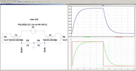
To test my intuition, I just set-up an LTspice simulation. I chose a 12V voltage source that turns on at $t=1\,\mathrm{s}$ and then off at $t=51\,\mathrm{s}$.

I neglected the resistance of the wire, and I set the transmission line delay to $0.5\,\mathrm{s}$ and the characteristic impedance to $Z_0=881\,\Omega$.

To get a reference node, I split the $144\,\Omega$ resistance of the bulb into two $72\,\Omega$ resistors.

Here's the result of the transient simulation:

enter image description here

See that the bulb current jumps at $t=1\,\mathrm{s}$ (at this resolution) when the voltage source turns on and then increases in steps (as the reflections make it back from the far ends) towards the DC steady state value up until the voltage source turns off.

As I expected, the initial voltage across the bulb is given by the voltage divider formed by the bulb's resistance and the characteristic impedance the two transmission lines:

$$V_{bulb}(1) = 12\,\mathrm{V} \frac{144}{881 + 881 + 144}\approx 0.91\,\mathrm{V}$$

(to be continued)


OK, there's a new video from Veritasium with an actual experiment as well as a nod to those that pushed back here. I haven't perused it but I'm looking forward to any new Q & A here.

5

I have a lot of respect for Derek Muller and his Veritasium videos. His central thesis in the video referenced above--that it is the electromagnetic fields, and not the electrons, that carry energy--is correct. However, the explanations and examples presented in the video are misleading on a fundamental issue of what the Poynting vector actually represents. And his answer to the underlying thought experiment is only 'right' in the most generous of interpretations.

First and foremost is Derek's explanation of the Poynting vector. He states (around the 4:26 mark):

"[John Henry] Poynting works out an equation to describe energy flux. That is, how much electromagnetic energy is passing through an area per second. This is known as the Poynting vector... The formula is really pretty simple. It's just [$\mathbf{S}=\frac{1}{\mu_0}\mathbf{E}\times\mathbf{B}$]."

However, this is misleading because "$\mathbf{S}\!=$" above is only just a definitional/shorthand notation and not really a 'formula' per se. The actual formula (known as "Poynting's Theorem") is a statement about energy conservation and is derivable directly from Maxwell's equations: $$ \mathbf{\nabla}\cdot\mathbf{S}+\mathbf{H}\cdot\frac{\partial\mathbf{B}}{\partial t}+\mathbf{E}\cdot\frac{\partial\mathbf{D}}{\partial t}=-\mathbf{E}\cdot\mathbf{J}. $$ For an electromagnetic plane wave (e.g., light) propagating in free space, $\mathbf{J}=0$ and Poynting's theorem aligns with the intuition that $\mathbf{S}$ is related to the time-varying electric and magnetic fields of the plane wave, and corresponds to the direction and rate of power of the plane wave. So Derek's description of energy coming to us from the Sun (~4:14 mark) is correct in this context, because such light is comprised (to first-order) of time-varying plane waves.

However, he goes on to state (around the 5:38 mark):

"But the kicker is this. Poynting's equation doesn't just work for light. It works anytime there are electric and magnetic fields coinciding. Anytime you have electric and magnetic fields together, there is a flow of energy and you can calculate it using Poynting's vector."

This is the crucial statement that begins to depart from the truth. While Poynting's Theorem always holds true (in the model of classical electrodynamics at least), it is not true that the Poynting vector (what Derek refers to as "Poynting's equation") always represents or describes the energy flux. I can only best describe this by quoting from Jin Au Kong's Electromagnetic Wave Theory textbook (2000 edition), which states it best in P1.3.3:

P1.3.3 $\ $The interpretation of $\mathbf{S}=\mathbf{E}\times\mathbf{H}$ as power flow per unit area at a point in space is a very useful and experimentally verified concept in electromagnetic wave theory. However, strict adherence to such interpretation in total disregard of Poynting's Theorem may lead to paradoxical results.

Kong goes on to provide an example: consider a charged particle placed next to a permanent magnet. Is there power flow due to the electric field $\mathbf{E}$ generated by the charged particle and the magnetic field $\mathbf{H}$ generated by the magnet? The answer is no--the net power flow is zero for static electric and magnetic fields in the absence of currents, and Poynting's Theorem shows this. This answer also delves into this issue a little. The moral of the story is to simply be careful in using the Poynting vector static-field situations, such as the simple DC battery circuit (beginning around 6:10) of Derek's video. David Griffith's popular Intro to Electrodynamics textbook also comments on this (see footnote 1 on page 347 of Edition 3--commenting that Poynting's integral form relates the Poynting vector passing through a closed surface, but "does not prove that [it] is the power passing through any open surface").

Second, his answer that it would take $1/c$ seconds for the light bulb 1 meter away from a battery "to light up" is only correct in the most extreme and generous of interpretations of the problem. Whether or not one assumes the wires are superconductors having no resistance, the problem can essentially be viewed as placing two linear antennas (having length 300,000 meters) 1 meter apart from each other, because the short-circuited ends don't play a part for the first second. If one were to actually replicate this in the real-world, then (1) the amount of radiative power for such a linear antenna would be very small (even less if the wires are lossy), and (2) the amount of 'received' power by the opposing wire/antenna having the light bulb would be even smaller (remember, radiative power for a quasi-infinite linear antenna decreases inversely proportional to the radial distance from the antenna). I doubt, even for a superconductor, that the bulb would light up.

Stephen K.
  • 161
  • 4
1

Let's say the switch is on, and the bulb is glowing. Now we turn the switch off. Now we can easily understand that the bulb keeps on shining while draining all the stored energy from the long wires, or from the space around the long wires.

Let's say the energy flows at speed of light in the wires, or around the wires.

For about two seconds the bulb glows almost normally, if the switch is one meter away from the bulb.

For at least one second the bulb glows perfectly normally, if the switch is one light second away from the bulb.

Isn't this quite intuitive?

Now we just need to time-reverse that what happened when we turned the switch off. Laws of physics are time-reversal symmetric. The time-reversed turning off the switch process is then the correct turning on the switch process.

So we can see that it takes a long time for the bulb to light up, not a short time as the video claims.

stuffu
  • 2,374
-1

The conclusion of the video is incorrect. The lamp will not glow after $\Delta t = \frac{d}{c}$ where $d$ is the distance between battery and lamp.

There is some valid concepts:

  1. Electromagnetic travelling waves propagate at speed $c$ in the vacuum, and energy is transported in the direction of the Poynting vector.

  2. In an electric circuit where a battery is connected to a lamp by conduction wires of negligible resistance, the direction of the Poynting vector is such to show a source of EM energy in the battery and a sink in the lamp.

It doesn't follow from $1$ and $2$ any assumption about speed of propagation of the electrical energy in the circuit. EM radiation propagates at speed $c$ and carries energy, but the EM energy in the circuit doesn't propagate as a wave directly from battery to lamp. It follows the circuit. It is a propagating EM field, but not an EM wave.

One difference for example is the phase shift between $E$ and $B$. Both fields are in phase for an EM wave, but not in a wire. After closing the switch, the current in the wire will grow in a rate depending on its inductance. The magnetic field around them will only reach its maximum after this transient to the maximum current. While $B$ increases, $E$ decreases, reaching zero in the steady state.

I am supposing all resistance in the lamp for that analisys.