When is an inverter NOT an inverter? (Pun intended.)
Understand that digital is a subset of analog. Digital logic is a collection of rules, which, when a system obeys them, can be used to synthesize digital logic circuits much faster and more reliably than is possible with fully continuous analog circuitry. Most commonly: when we don't need to simulate capacitor charges and whatnot, but can approximate their effect as time delays instead.
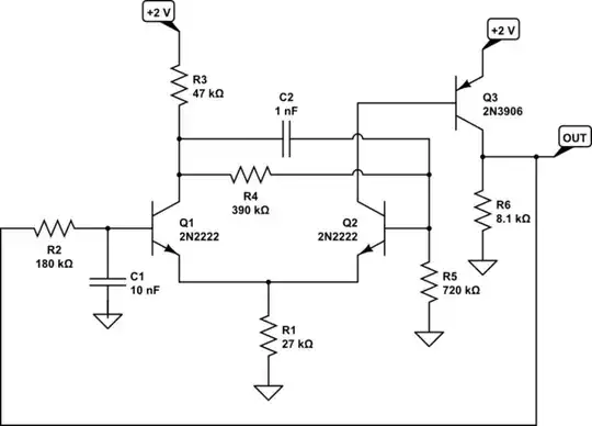
A single-stage inverter, as you can see here, isn't a very good inverter at all. Its output voltage varies continuously with the input voltage (slowed considerably by the capacitor attached to it); it's more of an amplifier than a logic gate.
The assumption that has been violated here, is that the input is a clean digital logic level. If it were, the output could be as well. But there's no capability of correcting such violations
If you chain together three in a row (inverters that is, without the large capacitors), you can increase gain enough that you might not mind the slow input; the output won't be strictly a pure logic level, but it'll at least be moving fast enough (say 100x the input) that it's recognizably "square".
Or you can use a Schmitt trigger circuit; basically as above, but with a feedback resistor from the 3rd stage output to the 2nd stage input, enough so that the positive feedback effectively raises its gain beyond infinity. (Obviously, this breaks the linearity assumption underlying the mechanism of feedback loops, and we get a different behavior instead.) This nonlinear effect (hysteresis) works particularly well to convert slowly-varying or indeterminate inputs to reasonable logic levels.
But now you've tripled the component count, roughly, and it's a lot less satisfying, say, if you wanted to build this on the breadboard or whatever?
This explanation extends to logic gates proper, as well: we are fairly picky about our logic gates, and want to see well-behaved outputs as much as possible, even if we're being loose with our input voltages, or output fanouts. This is why most gates are buffered, meaning additional NOT gates are added at the inputs and outputs, to better isolate the core logic function from the real physical input and output signals. Any generic CD4xxxBE or SN74HCxx(x) or etc. part you find (minus the partly-analog ones like timers and PLLs, but only at the analog-facing pins) will have these features.
There are still special cases where it's nice to have single naked inverters, and these are available usually in -U variants, e.g. CD4069UBE, 74HCU04. They're handy for making cheap amplifiers, crystal or other oscillators, etc. If you use one to make a ring oscillator as above, you will find exactly the same symptom. :)


Hearth's answer: Ohhh I see that now. this is a common emitter amplifier. So with my setup, I can only obtain a sinusoidal waveform? What technique, if there is one, can I use to obtain a squarewave at the output?
– help_me_learn Nov 27 '23 at 04:53I don't know if this is a question for this forum still but is it possible to use complementary logic with BJT or does this only work with MOSFET? I have tried it with NPN and PNP stacked together in push-pull form but did not get an output on LT SPICE.
– help_me_learn Nov 28 '23 at 01:33