I'll write up something for you -- a problem and a solution. I'll make it tricky, but real. In fact, I just posted up this schematic a day or two ago. So it is fresh in mind. It may look like it should boggle your mind. But if you get over how complex it may look at first and instead just sit down and label things in a perfunctory manner, you'll see that it is solvable with the tools you likely already have. If not, what's missing will stick out and at least you'll know what to work on.
It's good to challenge yourself. So let's do it.
Let's start by taking a diagram from this answer of mine, where this schematic was presented and discussed as a Schmitt trigger oscillator.
But this isn't about why it oscillates. We just want to get an idea of what the DC biasing point might look like without the capacitors complicating our lives. You can and should try to do that when the circuit itself seems overly complex with capacitors and inductors added to it. You don't need to know how it acts as a super-sophisticated FM transmitter. Because every working circuit needs to have a DC biasing point upon which to work. And you can ignore the complicated stuff and just focus on that: the DC biasing. It's a starting point for everything else.
Okay. So here's the diagram, with annotations I've made to help you see what I see.
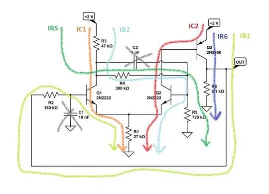
Your first task is to make sure that you follow all the colored lines of currents. This should cover all of them. (I hope I didn't mess up.) This is just about making sure to list everything we (you and I) can see as possible routes from the supply rail down to ground. I've tried to label them, appropriately.
Let's make a leap of faith and assume that \$Q_1\$ and \$Q_2\$ are in active mode. We'll also assume that \$Q_3\$ is also in active mode, for now.
(That \$Q_3\$ assumption can be tested. If it turns out that \$R_6\cdot I_{R_6}\ge 2\:\text{V}\$ then we know there's a problem assuming \$Q_3\$ is active and it must instead be saturated. But save that thought for later.)
Each of these current paths shown provides a KVL path and therefore also a KVL equation. We have six colors so six currents. Luckily, we know a few things about some of them, assuming active mode behavior (we'll assume that all three BJTs have the same \$\beta\$):
$$\begin{align*}
I_{C_1}&=\beta\cdot I_{B_1}\\
I_{C_2}&=\beta\cdot I_{B_2}\\
I_{C_3}&=I_{R_6}+I_{B_1}\\&=\beta\cdot I_{C_2}\\&=\beta^2\cdot I_{B_2}\\
V_{_\text{OUT}}&=R_6\cdot I_{R_6}
\end{align*}$$
So, the independent unknown ones are just \$I_{B_1}\$, \$I_{B_2}\$, and \$I_{R_5}\$. Note that \$I_{R_6}=\left(\beta^2-1\right)\cdot I_{B_2}\$, so it's dependent and not independent. I added that last one about \$V_{_\text{OUT}}\$ for later. Make sure you agree with it, too.
I think this means we just need three equations for that mess. Let's call \$V_{_\text{CC}}=2\:\text{V}\$ and write things out symbolically:
$$\begin{align*}
V_{_\text{CC}}-R_3\cdot\left(I_{R_5}+I_{C_1}+I_{B_2}\right)-R_4\cdot\left(I_{R_5}+I_{B_2}\right)-R_5\cdot I_{R_5}&=0
\\
V_{_\text{CC}}-R_3\cdot\left(I_{R_5}+I_{C_1}+I_{B_2}\right)-R_4\cdot\left(I_{R_5}+I_{B_2}\right)-V_{_{\text{BE}_2}}-R_1\cdot\left(I_{C_1}+I_{C_2}+I_{B_1}+I_{B_2}\right) &=0
\\
V_{_\text{OUT}}-R_2\cdot I_{B_1}-V_{_{\text{BE}_1}}-R_1\cdot\left(I_{C_1}+I_{C_2}+I_{B_1}+I_{B_2}\right) &=0
\end{align*}$$
Well, that seems like it might work.
We have to guess a bit about \$V_{_{\text{BE}_1}}\$ and \$V_{_{\text{BE}_2}}\$. And I'll get to how to think in more detail about it, momentarily. But for now small signal silicon BJTs (and this circuit isn't using any power BJTs) tend to have values that span from no less than \$400\:\text{mV}\$ to no more than \$900\:\text{mV}\$ and for every order of magnitude in their collector currents the values only vary by \$60\:\text{mV}\$. We can start with \$700\:\text{mV}\$ and make minor adjustments, if we care to, later.
So, let's plug in all that stuff and see what happens. (Yes, in cases like this you really do want to use a solver. Matrix solutions, or using Cramer's rule by hand, is tedious (and pointless, these days, unless you plan spending a lot of time on a desert island.)
But before we do that, let's do a Spice run to get some "real numbers" from a program using very sophisticated models for the transistors:
Ib(Q1):  6.76747e-08     device_current
Ib(Q2):  2.8755e-09      device_current
I(R5):   1.17565e-06     device_current
Ic(Q1):  1.35854e-05     device_current
Ic(Q2):  5.78305e-07     device_current
V(out):  0.940346        voltage
I(R6):   0.000116092     device_current
Okay. With that in hand to check ourselves, I'll use freely available SymPy and SageMath and Python applied to our simplistic idea of a BJT base-emitter junction voltage:
eqkvl1= Eq( vcc - r3*(ir5+ic1+ib2) - r4*(ir5+ib2) - r5*ir5, 0 )
eqkvl2= Eq( vcc - r3*(ir5+ic1+ib2) - r4*(ir5+ib2) - vbe2 - r1*(ic1+ic2+ib1+ib2), 0 )
eqkvl3= Eq( vout - r2*ib1 - vbe1 - r1*(ic1+ic2+ib1+ib2), 0 )
eqic1= Eq( ic1, beta*ib1 )
eqic2= Eq( ic2, beta*ib2 )
eqir6= Eq( ir6, (beta**2-1)*ib2 )
eqvout= Eq( vout, r6*ir6 )
for u in solve( [ eqkvl1, eqkvl2, eqkvl3, eqic1, eqic2, eqir6, eqvout ],
    [ ib1, ib2, ir5, ic1, ic2, vout, ir6 ] ).items(): u[0],
        u[1].subs( { r3:47e3, r4:390e3, r1:27e3, r5:720e3, r2:180e3, r6:8.1e3,
                     beta:200,vcc:2,vbe1:.7,vbe2:.7 } )
(ib1, 4.67679857705329e-8)     # Ib(Q1): 6.76747e-08
(ib2, 3.02050883890654e-9)     # Ib(Q2): 2.8755e-09
(ir5, 1.34750300034087e-6)     # I(R5):  1.17565e-06
(ic1, 9.35359715410658e-6)     # Ic(Q1): 1.35854e-05
(ic2, 6.04101767781308e-7)     # Ic(Q2): 5.78305e-07
(vout, 0.978620397684124)      # V(out): 0.940346
(ir6, 0.000120817333047423)    # I(R6):  0.000116092
Not too bad. Certainly, it doesn't look like we were crazy-off on anything. It's all within reason of each other, I think. Not bad for some guess-work.
But from the above, I can see that the collector currents are pretty small. About 1000 and 10000 times smaller than is appropriate for \$700\:\text{mV}\$ base-emitter junction voltages.
This means I'm off by about \$3\cdot 60\:\text{mV}=180\:\text{mV}\$ for \$Q_1\$ and by \$4\cdot 60\:\text{mV}=240\:\text{mV}\$ for \$Q_2\$. So let's make those adjustments and see if we get nearer to Spice:
for u in solve( [ eqkvl1, eqkvl2, eqkvl3, eqic1, eqic2, eqir6, eqvout ],
    [ ib1, ib2, ir5, ic1, ic2, vout, ir6 ] ).items(): u[0],
        u[1].subs( { r3:47e3, r4:390e3, r1:27e3, r5:720e3, r2:180e3, r6:8.1e3,
                     beta:200,vcc:2,vbe1:.7-.18,vbe2:.7-.24 } )
(ib1, 6.81463693311111e-8)     # Ib(Q1): 6.76747e-08
(ib2, 2.83175168651518e-9)     # Ib(Q2): 2.8755e-09
(ir5, 1.17388647605925e-6)     # I(R5):  1.17565e-06
(ic1, 1.36292738662222e-5)     # Ic(Q1): 1.35854e-05
(ic2, 5.66350337303036e-7)     # Ic(Q2): 5.78305e-07
(vout, 0.917464609242258)      # V(out): 0.940346
(ir6, 0.000113267235708921)    # I(R6):  0.000116092
The adjustments did improve things. I'd say it got closer to Spice's results.
For not actually being a Spice program and just using some very simple ideas and a solver program to do the heavy lifting so we don't have to, I'd say we got very close, in fact.
Now, let's really test the simplistic logic we applied. (Keep in mind that we are not doing anything like what Spice does. We are keeping everything relatively simple.) But let's now use the actual values for the base-emitter junctions that Spice came up with and see what we get from our very simplistic model. (Our model is nothing close to taking into account details, such as the BJT Early Effect, that Spice does handle. But no harm in seeing if our simple-minded analysis holds up still better with the values that Spice actually used.)
From the above Spice run I find \$V_{_{\text{BE}_1}}= 0.543839\$ and \$V_{_{\text{BE}_2}}= 0.462142\$. So let's plug those in and see:
for u in solve( [ eqkvl1, eqkvl2, eqkvl3, eqic1, eqic2, eqir6, eqvout ],
    [ ib1, ib2, ir5, ic1, ic2, vout, ir6 ] ).items(): u[0],
        u[1].subs( { r3:47e3, r4:390e3, r1:27e3, r5:720e3, r2:180e3, r6:8.1e3,
                     beta:200,vcc:2,vbe1:0.543839,vbe2:0.462142 } )
(ib1, 6.79206081592215e-8)     # Ib(Q1): 6.76747e-08
(ib2, 2.90261058248650e-9)     # Ib(Q2): 2.8755e-09
(ir5, 1.17569390015451e-6)     # I(R5):  1.17565e-06
(ic1, 1.35841216318443e-5)     # Ic(Q1): 1.35854e-05
(ic2, 5.80522116497301e-7)     # Ic(Q2): 5.78305e-07
(vout, 0.940422317579909)      # V(out): 0.940346
(ir6, 0.000116101520688878)    # I(R6):  0.000116092
Darn, that's good! The only cheat we had to use to get that close was to pick off the actual base-emitter junction voltages developed by a very sophisticated Spice program. But we did that without involving anything like the crazy, insane level of detail that a Spice program applies.
(Turns out that Spice applied \$\beta\approx 201\$ to the BJTs and if I ran our simple model with that change, the numbers get closer still.)
The point in all this is that you can almost phone it in and get decent results. Just stay calm and look at what you are facing without fear. Mark out details. Go back over to see if you missed any, adding them as you catch them. And then go for it!!!
By the way, we've confirmed that \$Q_3\$ is actually in active mode! (See if you agree with me about it.)

I believe the factor of B is misplaced in the above equation. I need to understand that in order to go through the rest of your above comments I believe the factor of B should be in the numerator.
– Jeffrey Edward Messikian Nov 28 '23 at 19:31That web page, which is the basis of your explanation states that Vbb-Vbe=Ib*Rb
Rearranging this then yields
Ib=(Vbb-Vbe)/Rb
then assuming Ie is approximately equal to BIb .....
I do not understand how the following line is true/stated on that page Ie=(Vbb-Vbe)/(Rb/B)
If you look at the page, you see that depiction. I think it should really be Ie=(B*(Vbb-Vbe))/Rb
instead of whats shown. I think the B on that page is shown in the wrong place.Almost a typeo.
– Jeffrey Edward Messikian Nov 28 '23 at 21:12