0

In the control volume for a fluid moving with velocities $u$, $v$, and $w$ in the $x$, $y$, and $z$ directions, respectively, we observe that the bottom face of the control volume is subjected to three types of stresses,a normal stress and two shear stresses, as shown in the following figure: enter image description here
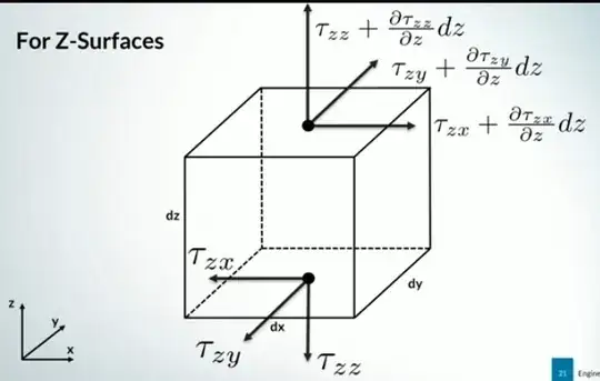
I will focus here on the shear stress, which is expressed by the following relation:

$$\tau_{zx} = \mu \left( \frac{\partial u}{\partial z} + \frac{\partial w}{\partial x} \right)$$

Before encountering this relation, I expected it to be as follows:

$$\tau_{zx} = \mu \left( \frac{\partial u}{\partial z} \right)$$

This is because I believe that the shear stress acting on the bottom face of the control volume arises due to the effect of friction between the parallel layers. Therefore, the velocity difference $u$ in the $z$-direction seemed acceptable to me as a cause of this friction. However, what raises my question is the presence of the derivative $ \frac{\partial w}{\partial x} $ in the relation, as I cannot visualize the effect of the velocity difference in the layers perpendicular to this face on the shear stress.

Can someone explain the reason for including this term $ \frac{\partial w}{\partial x} $ in the relation and its effect on the shear stress? I would like to get an explanation that helps me adjust my perspective and understand this point better.
1 Answers1

1

(Asked previously, but the asker did not find a satisfactory explanation.)

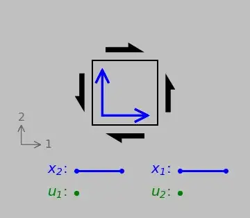
One way to look at it: A difference in the velocity $w$ in the $x$ direction would produce the same shear stress state as a difference in the velocity $u$ in the $z$ direction, the essence of shear being a change in the side angles and shape of an infinitesimal element.

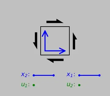
(Animations show a 1-direction load acting on the 2-direction face and a 2-direction load acting on the 1-direction face, with infinitesimal deformations shown as finite for visual clarity; replace 1 and 2 with your $x$ and $z$ axes, respectively. You can ignore the $x$ and $u$ lines; these are intended for a discussion of strains in terms of vector lengths and tip movements.)

See also this discussion for another way to look at it: Conservation laws require both $\frac{\partial u}{\partial z}$ and $\frac{\partial w}{\partial x}$ to be equally and symmetrically incorporated.

Edit: There was a question about whether the top and right forces, say, can each be labeled $F$ and combined to give a resultant of $\sqrt{2}F$, pointing to the top-right. The forces are intrinsically linked to the faces through the stress tensor; to properly reorient the element by 45°, we would transform the tensor by premultiplying and postmultiplying a rotation matrix:

$$\boldsymbol{\sigma^\prime}=a\boldsymbol{\sigma}a.$$

where $$a=\left[\begin{array}& 1/\sqrt{2} & 1/\sqrt{2} \\ 1/\sqrt{2} & 1/\sqrt{2}\end{array}\right].$$

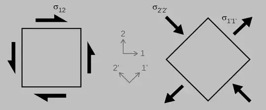
(An alternative graphical approach is Mohr's circle.) The reoriented element is subjected to equal compressive and tensile loads on the rotated faces, where the magnitudes of $\sigma_{12}=\tau_{12}$, $\sigma_{1^\prime 1^\prime}$, and $\sigma_{2^\prime 2^\prime}$ are all equal:

This is also a way of indicating a pure shear state, as is any other transformation using a different angle than 45°.

So the answer is no, we can't resolve the forces independently; we have to apply the correct tensor transformation rules.