What the voltmeter reads in this case is not the classical voltage drop as the concept of voltage itself, as a scalar function whose gradient gives the field, becomes redundant. What it displays is, indirectly, the current through it, which in the case of induced emfs, is not related to "potential drop" across its end. (it will display $V$ as its reading where $V=Ir$, $I$ the current through it, and $r$ the resistance of the voltmeter.
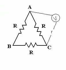
As an example, consider the case you present in the question. Three resistors of resistances $R=5$ each are connected to form a triangle. A voltmeter of resistance $r=100$ is connected across two vertices. Let the change in magnetic flux be confined to the triangular portion only, and be $1 weber/s$. Therefore, the line integral of the field along a line which completely includes the area with changing magnetic flux must be $1 volt$. Let the current through the voltmeter be $I_1$(from A to C) and across the two resistors (except the one across which the voltmeter is attached) be $I$(clockwise). The current through the resistance across which the voltmeter is connected is $I-I_1$(from A to C).
 First, consider, the line integral along the triangular portion in clockwise manner. The integral will give
$$-2IR-(I-I_1)R=1$$
$$-15I+5I_1=1$$
Considering the line integral along $C\rightarrow B\rightarrow A\rightarrow \text{Voltmeter}\rightarrow C$ clockwise, we get
$$-2IR-I_1r=1$$, since in both the case the change in magnetic flux (time rate of change) is same, as the change is confined to the triangular area which is bound completely by both the line integrals.
$$-10I-100I_1=1$$
on solving we get $I=21/310=0.068$(anticlockwise) and $I_1=1/310=0.0032$(anticlockwise). Therefore the voltmeter will show $I_1r=0.32V$ which is equal to $(I-I_1)R$ but not $2IR$ since, in cosidering the voltmeter attached to only the resistance $AC$, we get a simple circuit without any changing magnetic flux, but considering the voltmeter as being attached to the resistances $CB$and $BA$, we get a circuit which has a changing magnetic flux, which needs to be accounted for, and hence reading will not be according to $2IR$, or the hypothetical "potential drop" across the two resistors.
First, consider, the line integral along the triangular portion in clockwise manner. The integral will give
$$-2IR-(I-I_1)R=1$$
$$-15I+5I_1=1$$
Considering the line integral along $C\rightarrow B\rightarrow A\rightarrow \text{Voltmeter}\rightarrow C$ clockwise, we get
$$-2IR-I_1r=1$$, since in both the case the change in magnetic flux (time rate of change) is same, as the change is confined to the triangular area which is bound completely by both the line integrals.
$$-10I-100I_1=1$$
on solving we get $I=21/310=0.068$(anticlockwise) and $I_1=1/310=0.0032$(anticlockwise). Therefore the voltmeter will show $I_1r=0.32V$ which is equal to $(I-I_1)R$ but not $2IR$ since, in cosidering the voltmeter attached to only the resistance $AC$, we get a simple circuit without any changing magnetic flux, but considering the voltmeter as being attached to the resistances $CB$and $BA$, we get a circuit which has a changing magnetic flux, which needs to be accounted for, and hence reading will not be according to $2IR$, or the hypothetical "potential drop" across the two resistors.