I have been trying to understand some practical applications of $LC$ oscillators and I can't seem to find much information available on the net. One consistent application that I see is "$LC$ circuits are used for generating signals at a particular frequency" without much details. Can someone please explain some applications of $LC$ oscillator, or how they are used for generating signals at a particular frequency?
Asked
Active
Viewed 1,031 times
5 Answers
0
This is described in great detail on wikipedia
An LC circuit, oscillating at its natural resonant frequency, can store electrical energy. See the animation at right. A capacitor stores energy in the electric field (E) between its plates, depending on the voltage across it, and an inductor stores energy in its magnetic field (B), depending on the current through it.
If an inductor is connected across a charged capacitor, current will start to flow through the inductor, building up a magnetic field around it and reducing the voltage on the capacitor. Eventually all the charge on the capacitor will be gone and the voltage across it will reach zero. However, the current will continue, because inductors oppose changes in current. The current will begin to charge the capacitor with a voltage of opposite polarity to its original charge. Due to Faraday's law, the EMF which drives the current is caused by a decrease in the magnetic field, thus the energy required to charge the capacitor is extracted from the magnetic field. When the magnetic field is completely dissipated the current will stop and the charge will again be stored in the capacitor, with the opposite polarity as before. Then the cycle will begin again, with the current flowing in the opposite direction through the inductor.
The charge flows back and forth between the plates of the capacitor, through the inductor. The energy oscillates back and forth between the capacitor and the inductor until (if not replenished from an external circuit) internal resistance makes the oscillations die out.
Such circuits make up a great deal of electrical applications, obviously oscillators, filters etc.
https://en.wikipedia.org/wiki/LC_circuit#Applications
EDIT: Okay, so some uses for a resonating/oscillation circuit is to create devices where such behaviour is wanted.
If we step away from the LC-circuit and observe the oscillator instead, which seems to be what your questions is really about, we have a vast number of different applications.
Mixers are one possible application, used in microwave engineering. Let's say we're using a radiometer to measure gas emission at roughly $100$ GHz. This is a very high frequency and electronics to analyze and filter at this frequency is hard to create and is most often very costly. What one could do then is to downconvert the signal to a lower frequency with the same information, using a mixer. A mixer is basically an oscillator that the received signal is ran through which downconverts the frequency to something lower $$f_{IF}=|f_{RF}-f_{LO}|$$ where IF is the new frequency (intermittent frequency), RF is the receoved frequency and LO is the frequency of the local oscillator. Worth noting here however is that this equation has two solutions, there are two frequencies that produce the same IF-frequency, so filtering needs to be done to filter away the unwanted one.

Image borrowed from https://www.electronics-notes.com/articles/radio/superheterodyne-receiver/image.php
Another possible use for oscillators are of course signal generators. The amount of possible applications are endless.
DakkVader
- 2,113
0
The impedance of reactive components, inductors and capacitors, depends on the frequency in opposite ways.
For inductive circuits, the magnitude of impedance increases with frequency and the phase of the current lags behind the phase of the voltage.
For capacitive circuits, the magnitude of impedance decreases with frequency and the phase of the current leads the phase of the voltage.
When a capacitor and an inductor are combined in the same circuit, they have opposite effects on the impedance of the circuit and, at some, resonant, frequency, their contributions cancel each other, resulting in a purely resistive impedance and zero phase shift.
For an LC oscillator to oscillate, its feedback signal has to be in phase with its input signal, so that these two signals add up (positive feedback). This phase alignment will happen only at a particular, resonant, frequency of the LC circuit at the core of the oscillator. As a result, the LC oscillator will oscillate at this particular frequency.
V.F.
- 12,353
0
One way of seeing this is to note that when an active two-port circuit such as an amplifier is terminated wrongly, not matched, it usually goes into some kind of oscillation because the load reflects the energy back to the source, and then that goes back and forth. The rate of that "back and forth" is the oscillation frequency and it has to be controlled by explicit means to be useful. A resonating LC circuit is such a reactance that restricts over broad range of terminations the possible frequencies of oscillation. That it be reactive, i.e, lossless is important not just restrict the range of possible frequencies but also thereby to reduce the noisiness of the signal. The more reactive and narrower the resonator is the purer the oscillation becomes.
hyportnex
- 21,193
0
LC tank circuits are commonly used in oscillators, especially for radio applications. The LC circuit is connected to an amplifier, often a transistor, in a positive feedback configuration. The positive feedback allows self-sustaining oscillations, while the LC circuit selects the frequency at which oscillations can happen. See Colpitts and Hartley oscillators for typical examples.
You can also use a passive RLC circuit to filter the input frequency and give you an output signal at the desired frequency. This could be a way of tuning the receive frequency of your radio. For instance, if you apply the input signal across a series RLC circuit, at the resonance frequency of $2\pi/\sqrt{LC}$, the total impedance will be purely resistive and the voltage across the resistor will be maximum. As you change the frequency, the reactive impedance of the LC circuit will rapidly increase and the output voltage across the resistor will get smaller.
Puk
- 14,100
0
One consistent application that I see is "LC circuits are used for generating signals at a particular frequency" without much details.
LC circuits oscillate at a specific frequency, which is crucial generating and detecting radio waves:
- Generating oscillations: in a generator the oscillations in a circuit would be typically amplified using a non-linear element, with the power coming from battery. The DC voltage bias from battery is thus converted into oscillations at a required frequency. The simplest system of this type is Van der Pol oscillator, although, as is often the case, the circuit diagrams can be rather confusing:
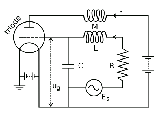
This image shows a van der Pol oscillator forced by an already oscillating source $E_S$. One can easily recognize the RLC curcuit in the middle, whose frequency is typically different from that of the driving source. Without absence of driving source $E_S$, the oscillator would perform oscillations at its own frequency, $\omega_0$ - losing energy in resistance, but having it replenished by the buttery and the triode, which assures that the battery aids in the forward, but not the backward part of the oscillation cycle.

Driving causes a phenomenon of synchronization, where the oscillator starts generating (potentially strong) signal at a the frequency of the driving source (which can be rather weak.) This phenomenon is used in, e.g., synchronizing electric power grids (which is, strictly speaking, an application outside of the domain of radio).
- Detecting oscillations Application of LC circuit in detecting radio waves is conceptually much simpler (image source):
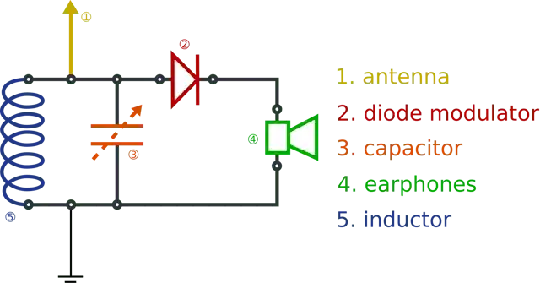
The LC circuit here is excited only by the oscillations around a particular frequency, selecting them from all the signal affecting the antenna - thus, by tuning the capacitance or inductance of the LC circuit we can tune to a particular station. Note that the signal of interest is not the high carrying frequency, but the signal by which it is modulated (music or speech). The non-linear element (the diode) serves as a detector to extract the modulating signal and average out the carrying frequency, restoring the signal of interest, played via the loudspeaker/headphones.

Related: Quantum description of radio antenna
Roger V.
- 68,984