33

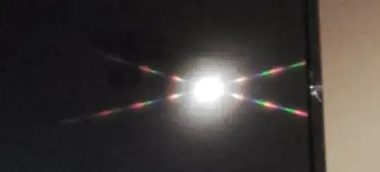
If you shine a laser pointer or generally any coherent light at the screen of a fancy, new TV, you get a very sharp X pattern.

enter image description here

I think this is a property of LED screens specifically. This phenomenon has been noted many times (1, 2, 3, 4), but every single answer is unsatisfactory, because they all say "it's a diffraction grating".

If the TV screen were like a two-dimensional diffraction grating, there would be a two-dimensional grid of points in the diffraction pattern; that is the universal pattern you get from scattering off a crystal or a phone screen. But I've never been able to see any points in this grid besides the X itself, even in good photos like the one above; it's impossible for such a sharply non-grid like pattern to be produced by diffraction of a two-dimensional grid.

Searching around, I've seen a lot of discussion on the internet about this, but no resolutions. I suspect the effect is due to something like single slit diffraction off of small features in each pixel. (Since larger things make smaller diffraction patterns, in this case the two-dimensional grid would still be there, but too small to see.) But it may be more complex; these pixels are quite complicated optical components.

Does anyone know precisely what causes this pattern?

knzhou
  • 107,105

3 Answers3

9

As we know, diffraction pattern is a Fourier image of the grating. In your case the pattern looks very much like two crossed patterns from usual 1D gratings symmetric along one of the directions (like in many-slit experiment). If we try to find inverse Fourier transform of an artificially-made pattern similar to the one on the picture in the OP, we'll see:

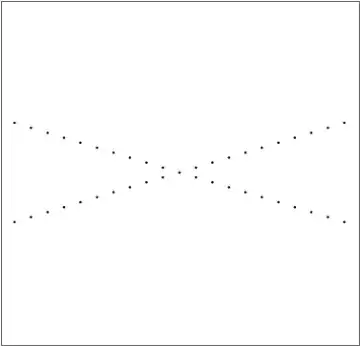
Diffraction pattern (intentionally padded with empty space to make the domain square):

diffraction pattern

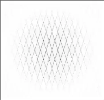
Its inverse Fourier transform:

inverse Fourier transform of the pattern above

So, the math says the same I was guessing above (and what the answer by flippiefanus was trying to tell). Now, what is actually making this pattern — that I can't tell for sure (I don't even know the model of your TV to do any research). My guess is that this might be the arrangement of the conductors powering the pixels. Or it may be the pattern from one of the layers of light spreading system of backlight (if it's not an OLED TV — these don't have backlight).

Ruslan
  • 30,001
  • 8
  • 70
  • 154
1

I can't give a complete answer and I haven't been able to reproduce the exact effect on any TVs in my home (of varying ages between 1 and about 12 years old) using a plain light (not a laser pen). All my screens are anti-glare rather than gloss.

The patterns I observe are a dominant plus-shaped pattern (which may be due to the LED light source in my case), and a much dimmer and fully symmetrical x-shaped pattern (not the compressed x-shape in your image).

I suggest that what you're seeing is the aggregation of "diffraction spikes" from reflections through the multiple rectangular apertures on the screen. This is a familiar effect in photography, for example.

https://en.wikipedia.org/wiki/Diffraction_spike

The lobes of the diffraction in the links given and the photo posted, are not fully symmetric partly presumably because the apertures themselves are rectangular on those screens - that is, because the pixels are taller than wider, there is a bias towards towards horizontal diffraction rather than vertical.

Incidentally, contrary to your assertion in your question, there are clear "points" in the diffraction which proves it is not from a single aperture. You can see this because there are repeating rainbows of diminishing intensity. The diffraction is obviously frequency dependent which is why the separate wavelengths are split out, but if there was only one point, then there would be at most one rainbow on each lobe.

Nor is it a one-dimensional pattern - it's clearly a pattern in two-dimensions.

EDIT:

Picture added to support comments below.

Diffraction grating

Steve
  • 3,164
0

Some basic physical considerations may provide a partial (qualitative) explanation. However, perhaps such a partial explanation would suffice here (?). The idea is to use one's basic understanding of diffraction to reverse the process. In other words, the question is what would the input field have to be to produce the observed diffraction pattern?

First, as a kind of reference, let's consider what would produce a grid of points in the diffraction pattern. For this purpose, let's assume the grid is perpendicular. At the end we may consider what would happen with other angles. In this case, one can write the grid of points (crudely) as the product of two functions $$F(x,y)=F_x(x) F_y(y) . $$ Since they are perpendicular, the Fourier transforms that produced the diffraction pattern would also operate independently on the two directions. So the source field would then also be a product of two functions $$F(x,y)={\cal F}\{g_x(u)\}{\cal F}\{g_y(v)\} . $$ The effect of an arbitrary angle can be introduced by an appropriate affine transform on the coordinates. By Fourier theorems, it then follows that one would have the inverse affine transform on the coordinates of the source function.

Now we consider the case where we don't have a grid, but rather an X. Again we start by assuming the legs are perpendicular. In this case, the diffraction pattern is a superposition $$F(x,y)=F_x(x) + F_y(y) . $$ So the source would have to be a superposition as well $$F(x,y)={\cal F}\{g_x(u)\}+{\cal F}\{g_y(v)\} . $$ Going to arbitrary angles, one then finds that the source field is still a superposition, but with the orientations of the independent variables of these functions not being orthogonal to each other. The source field is produced by being reflected off the front of the TV screen, while being multiplied by the reflectance. The reflectance is a periodic function along two directions. So, one can indeed think of it as two diffraction gratings, but instead of a multiplication of their transmission functions (or reflectance functions), we have the addition of their transmission functions.

The next thing is to use the qualitative nature of the amplitude variation along the legs of the X to determine the nature of the gratings. It is clear that there is some periodicity in this function, together with an overall envelop. One can model such a case (along $x$ for instance) by $$ F_x(x) = h(x)[p(x)\star C(x)] $$ where $C(x)$ is a pulse train (comb function); $\star$ represents convolution; $p(x)$ gives the shape of each pulse; and $h(x)$ is the overall envelop. The inverse Fourier transform would then give one the grating function $$g_x(u) = H(u)\star [P(u) C(u)] $$ where $P(u)$ and $H(u)$ are the inverse Fourier transforms of $p(x)$ and $h(x)$, respectively, and $C(u)$ is again a comb function. At this point one can start to identify the physical origins of all these functions: $H(u)$ governs the shape of each grating line, which is probably determined by the shape of the pixel of the TV screen; $P(u)$ gives the overall shape of the source field, which is probably related to the shape of the illuminated spot. If one can obtain quantitative information about the diffraction pattern, one can even determine more exactly what the function shapes of these functions are.

Hopefully, this provides a better understanding. The key is to realize that the diffraction pattern can indeed be formed by diffraction gratings, but where their transmission functions are added rather than multiplied.
flippiefanus
  • 16,824