First, your questions.
Q1: All else being ignored (early burn out of the LED, etc...) will the circuits consume the same amount of power?
No. Assuming a fixed supply voltage, the one without the resistor will consume more power because the current isn't being limited by the resistor. Instead, the current is limited ultimately by the power supply and/or the LED's internal resistance (at least up until the moment it becomes a 'fry-ode' and releases the magic smoke.)
Q2: in order to reduce the energy of this circuit, you'd have to do something like add a buck converter or PWM, correct?
You can limit the LED current with a dropping resistor to limit the power, and thus, energy used.
To improve efficiency, you need to reduce the supply voltage to the lowest possible to allow lower-value dropping resistor. Or, or use a constant-current DC-DC LED driver and no dropping resistor at all.
Using PWM will also reduce the overall energy consumption, but have limited improvement in efficiency. PWM has some downsides as well, including EMI noise and strobing effects.
Fun fact: it's possible to use much higher LED current at lower duty cycle to achieve the same average luminous power output, without killing the LED. For example, if you run a 20mA LED at 100mA and 20% duty, you achieve similar light output and higher perceived brightness compared to straight DC current. But it's not a huge win. (we'll explore that below.)
Nevertheless, many LED datasheets will give a max pulsed-current figure just for this reason.
A typical use case for high-current pulsed drive would be an IR remote, which drives the snot out of the IR LED at high peak current with a low-duty carrier. Because the IR output is being received by a sensor, and not a human eye, this substantially increases the reach of a remote control without increasing the power used. (Pro Tip: don't stare at an IR remote emitter with your eye - they're powerful enough to do some damage.)
Q3: what exactly does a resistor do with the energy it is removing from the circuit?
The purpose of the resistor is to set the LED current. The lower the resistor value, the higher the current in both itself and the LED, thus the more power is used, again in both. It's possible to use a resistor for current-setting because for most practical purposes, the LED forward drop (Vf) is a fixed voltage, so the LED current is simply I = (Vbat - Vf) / R.
The downside of using a resistor to set current is that the resistor dissipates power (wastes energy) that could otherwise be delivered to the LED. Where does the power go? The resistor sheds it as heat.
Now, how does the resistor value affect the amount of power wasted as a proportion of the total power used? Within a limited range of current, there will be little difference in LED efficiency vs. resistor value. This is because the IR drop of the resistor and LED don't change very much over the range of useable LED current. (We'll explore that in more detail below.)
What can you do to make an LED + resistor combo the most efficient?
- Use the lowest possible power supply to reduce required resistor IR drop.
- Use PWM and overdrive if the LED can handle it (and, the PWM doesn't cause other problems.)
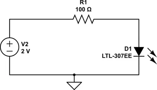
We noted that the resistor sets LED current. How?
Think of the LED as a fixed voltage drop (which, within reason, it is.) Kirchhoff’s voltage law tells us that the current-limiting resistor will have a fixed voltage drop, too.
Let's consider two cases of a red LED with a forward voltage (Vf) of approximately 2V.
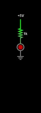
- Case 1: Resistor = 1k, Vbat = 5V
Current will be: I = (Vbat - Vf) / R = (5V - 2V) / 1k = 3mA
Resistor power will be 3mA^2 x 1k = 9mW
LED power will be 3mA x 2V = 6mW.
So the resistor is using 60% (3/5) of the power, while LED is using 40% (2/5). Makes sense, since they're seeing voltage drops of 3V and 2V respectively, out of a total of 5V.
Now let's consider the other extreme:
- Case 2: Resistor 1 ohm, Vbat = 5V
Current (simplistically) will be: I = (Vbat - Vf) / R = (5V - 2V) / 1ohm = 3A
Resistor power will be 3A^2 x 1ohm = 9W
LED power will be 3A x 2V = 6W.
Based on this simple fixed-Vf assumption we have the same story as the 1k ohm case: resistor power is 3/5 of the total, LED 2/5.
Conclusion? The ratio of resistor power to LED power is the same at both current extremes. Thus, both have the same relative 'efficiency'.
But we know that's not quite what actually happens. The LED forward drop increases with current. So at higher current, a larger portion of the power will be dissipated in the LED than is predicted by the simplistic assumption of fixed LED forward voltage.
Here's a chart that shows LED forward voltage vs. current, for various types of LEDs:

From http://lednique.com/current-voltage-relationships/iv-curves/
You'll see that the forward voltage shifts some as LED current rises. In the range shown it doesn't shift much, but it does. That's because like all semiconductor devices, LEDs in forward bias have an internal resistance that is limited by the LED substrate material itself. The bigger the LED chip, the less the Vf-vs-I shift.
Here's a quick simulation to illustrate this I-V behavior (simulate it here):
Falstad’s red LED model is similar to what’s shown in the chart above: Vf is about 1.8V at 20mA.
As you vary the slider between 1k down to 1 ohm, the scope plots will show you that the ratio of resistor power to LED power goes from about 2:1 down to 1:1, because the LED IR drop increases with current, much like we’d expect.
So in theory the lower resistance / higher current case is more 'efficient' since a larger portion of the total power is being shed in the LED.
As a practical matter over a reasonable constant DC current range (say, 0 up to 20mA) there it little to be gained efficiency-wise by running the LED at higher current.
You can get an efficiency improvement if you use the PWM 'overdrive' trick as I mentioned above. (I'll get into why this may be a Bad Thing in a moment.)
However, for ultimate efficiency, especially when driving a big LED, it's best to use a DC-DC constant-current driver instead of a resistor drop or using PWM. Then you avoid resistor losses entirely. While you still have some loss in the DC-DC (10-15% or so), it's still a win compared to a dropping resistor.
And now, the Bad Things about PWM.
On the electrical side, PWM switching can cause system noise issues and EMI radiation.
On the optical side, PWM strobing can be annoying, or even dangerous.
A major example where LED PWM is a cardinal sin is automotive lighting. Yet somehow many automakers still don't seem to 'get it' and continue to use PWM for exterior lighting (if you're reading this and this is your job, shame on you. Do better.)
First of all, PWM strobing becomes visible with movement. Guess what? Cars move, so other drivers see the flickering. This is at best distracting, at worst, seizure-inducing.
In a more narrow case, if you're unlucky enough to be tasked with filming a car equipped with with PWM-modulated LEDs, the strobing really messes up the footage, especially if your camera is a 'rolling shutter' type: you'll get 'banding' in your footage.
But here's where PWM becomes a hazard. LED PWM strobing can reduce the accuracy of object detection, critical for Autonomous Driving (ADAS) systems. For example, PWM strobing can influence detection of traffic light lights, reducing the effectiveness of emergency braking / collision avoidance. Imagine what PWM could do to brake light detection, an ADAS task even more time- and safety-critical than detecting a traffic light.
To combat this issue, some more recent automotive cameras have integrated anti-flicker technology to mitigate PWM artifacts. But there are plenty of ADAS cameras on the road that don't have this.


