0

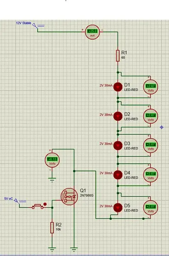
I'm facing to following problem: I need to turn on 5 LEDs (2 V, 30 mA) in series from a 12 VDC power supply using a MOSFET (2N7000G in this case). To calculate the resistor this formula was used:

12 V (power supply) - 5 x 2 V (series LEDS) = 2 V for resistor and MOSFET

From the datasheet: RDS(on) is 6 Ω: 6 Ω x 0.03 mA = 0.18 V voltage drop across the MOSFET.

2 V (from resistor and MOSFET) - 0.18 V (across MOSFET) = 1.82 V for resistor

U=IxR -> R=U/I -> R = 1.82/ 0.03 -> R = 60 Ω

If the circuit is designed with a 60 Ω resistor, the LEDs are energized only with 25 mA (even if 60 Ω should provide 30 mA from my calculations). Also, the voltage across the LEDs is increased to 2.07 V each (in the LED simulation the properties used are 2 V and 30 mA; I double checked all of them).

My opinion is that 0.07 V makes my calculation wrong, but why does this happen? What did I do wrong?
enter image description here

ocrdu
  • 9,195
  • 22
  • 32
  • 42
SkePsis
  • 65
  • 5
  • Link to LED datasheet please. – winny Jan 29 '24 at 17:51
  • I suspect that the 30 mA you quote for the LED current is the Absolute Maximum rating, beyond which the LED may be damaged. It is best to stay somewhat below that current. LEDs will work over a very wide range of currents, just getting dimmer at lower currents. You may find your LEDs are bright enough at a much lower current, like 10 mA. For one application I had to reduce the current for a green LED to under 1 mA to get the LED dim enough! – Peter Bennett Jan 29 '24 at 19:46
  • Is a OSRAM LSY T676 – SkePsis Jan 30 '24 at 09:12

2 Answers2

3

The assumption you make about the LED forward voltage being constant is not right. The simulation is modeling the LED, not what you're assuming its forward drop to be.

The LED datasheet forward voltage is usually stated at the nominal forward current (e.g., 20mA). However, the IR drop across the LED, when forward biased, will increase with current, as the diode itself has some internal resistance. The simulation is modeling this, based on some form of the Shockley Diode Equation.

This answer discusses the LED I-V relationship in further detail: Does a resistor in a simple LED circuit actually make it more efficient or does the resistor just burn off the energy?

Even then, that LED forward drop given in the datasheet is nominal. It can vary from LED to LED with process, and also vary with operating temperature.

You can adjust for this by modifying the series resistor. But, your resistor overhead voltage as a percentage of the total IR drop is kind of small, so repeatability will not be so great.

Note however that the perceived brightness difference between 25mA and 30mA will not be very much for a typical LED. If this is your only string to illuminate, it may very well be 'good enough' to just reduce the value of the resistor a bit to achieve your target 30mA current, assuming your LEDs are rated for that higher current.

But if having an exact, repeatable LED current (and therefore, brightness) matters to you, you need a current regulator to compensate for the non-ideal forward voltage behavior.

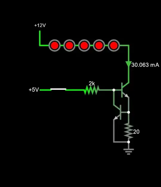
As it stands, you have enough overhead voltage (about 2V) that you could use a 2-transistor current limiter. With a small modification the current limiter can also serve as your low-side switch.

Example (simulate it here):

enter image description here

hacktastical
  • 53,912
  • 2
  • 49
  • 152
  • Thank you for complex answer. I want to control LEDs with a PWM signal coming form uC to change brightness. I was thinking about current regulator, but if I do this I think control of brightness will not work anymore., – SkePsis Jan 30 '24 at 09:21
  • 1
    Not so. With the circuit I’ve shown you can still use PWM to dim. The current will toggle between 30mA and 0mA with the toggle. – hacktastical Jan 30 '24 at 21:03
  • Perfect, I will. Thank you! Have you also a recommendation for that transistor? – SkePsis Feb 01 '24 at 08:04
  • 2N3904 or similar. – hacktastical Feb 01 '24 at 15:17
2

lousy regulation with a resistor in this case

Resistors make terrible current regulators for long chains of LEDs. Escpecially so when you leave only a small left-over voltage to work with. The LED current variation you will expect is:

$$\%I_{_\text{LED}}=\%V_{_\text{LED}}\cdot\frac1{\frac{V_{_\text{CC}}}{V_{_\text{LED}}}-1}$$

So, in your case this would be \$\%I_{_\text{LED}}=-5\cdot \%V_{_\text{LED}}\$.

LED voltages commonly vary by 10%. So this means in your case that could mean 50% variation in the current. (In the opposite direction, so if the LED string voltage increased by 10%, from \$10\:\text{V}\$ to \$11\:\text{V}\$, then the current would decrease by 50%.

This is really very bad for regulation.

On the plus side, using 5 LEDs tends to make the statistical variations a little better as variations of one LED have a chance of being compensated by variations of another one. But it is still quite risky with only 5 LEDs in the string.

use a current source/sink

With that much overhead, though, you can follow the advice given by hacktastical and use that technique for providing a decent current sink/source for the LED chain.

how to design a current sink

By the way, if you are looking to actually learn how to design one of those rather than just being given one -- one that will work in a predictable way over operating temperature and device variations -- then see this link to an EESE answer on this topic.

periblepsis
  • 8,575
  • 1
  • 4
  • 18
  • Thank you for information. I will read your topic and verify if I can do something suitable for PWM input - I still learning about this source/ sink and so on. – SkePsis Jan 30 '24 at 09:23
  • I try this current regulator with two 2N3904 but I have another issue when I want to turn OFF the circuit. Somehow I still have some volts in circuit - Is this normal? Is any method to avoid this ? Please see https://i.imgur.com/6mwMN5j.png – SkePsis Mar 04 '24 at 19:23
  • 1
    @SkePsis The input should be tied to ground through a resistor when inactive. What I see there is, instead, a PB switch that makes or breaks a connection to the MCU pin. But there's no pull-down resistor. So it can float. – periblepsis Mar 05 '24 at 09:42