1

I am designing an electronic load for a battery, and I don't want to use a single MOSFET that carries the entire current and has to be bolted to a large heat sink. So, I thought about connecting 3 MOSFETs in parallel to distribute the current and, consequently, the total power. However, despite searching for information on the correct connection of MOSFETs in parallel, I'm not very sure if I'm doing it correctly. Here, I show you the design I came up with.

enter image description here

Note:

  • The SET_VOUT signal has the wrong name; it should be SET_IOUT.
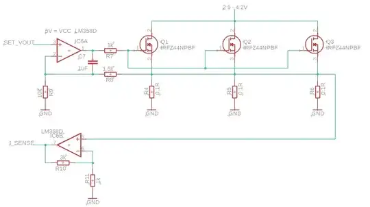
  • All values are the final values, meaning that these are the values I would solder into the circuit.
  • The op-amp's power supply is 5V.
  • I_SENSE is an analog signal to a microcontroller to measure the current in the electronic load (it seems obvious, but I mention it anyway).
  • The SET_VOUT signal has the wrong name; it should be SET_IOUT.
WalterPH
  • 440
  • 1
  • 10

2 Answers2

1
  • The op-amp's power supply is 5V 5V is not enough for IRFZ44N. The threshold gate-source voltage, VGS-th, is given 4V (max) for 0.25mA drain current but I'm assuming the drain currents are much higher in your application. Consider logic-level gate MOSFETs (i.e. having much lower VGS-th values) if you can't increase the supply voltage.
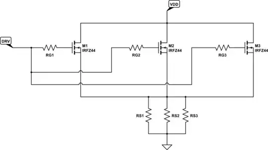
  • It's generally good to employ separate/individual gate stopper resistors rather than using one for all.

schematic

simulate this circuit – Schematic created using CircuitLab

  • The MOSFETs will never share the current equally. To increase the chance, attach the MOSFETs to the same heatsink i.e. never let one to get hotter/colder than others.
Rohat Kılıç
  • 33,940
  • 3
  • 29
  • 85
  • 2
    However, the MOSFET has a positive temperature coefficient, which tends to reduce current in the hotter MOSFET and keep currents to similar levels. https://www.sciencedirect.com/topics/engineering/positive-temperature-coefficient "The positive temperature coefficient of MOSFETS is responsible for increasing the resistance (because of heating) in the places where the current density is highest and therefore the current reduces. This mechanism ensures a uniform current density in the MOSFET." – Charles B. Cameron Nov 21 '23 at 14:43
  • @CharlesB.Cameron that's why you need to attach the MOSFETs to the same heatsinks (last item above). – Rohat Kılıç Nov 21 '23 at 14:47
1

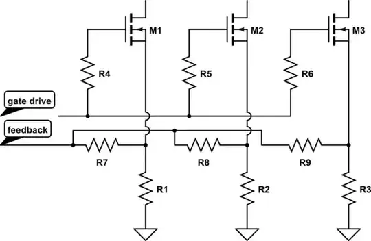
The most important thing to do is to split your source degeneration resistors, R1-R3. That way, if one FET is running a bit hot, it'll be less able to steal current from the other two. In order to get your current feedback, though, you'll need to isolate those nodes from each other -- that's the function of R7-R9.

Note that typical power FETs simply aren't designed for sustained operation with high \$\mathrm{V_{DS}}\$ -- so be careful about applying this circuit, and derate the transistors heavily (or use power BJT transistors, and a base driver that can supply enough current).

schematic

simulate this circuit – Schematic created using CircuitLab

TimWescott
  • 46,144
  • 1
  • 42
  • 107