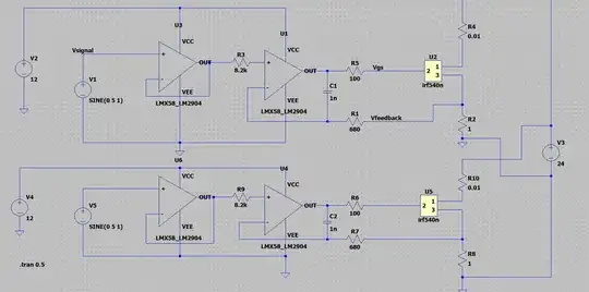
I am designing a programmable DC load using 120W MOSFETs available at my local store. Due to its limited power rating, I am planning to have 2-3 of them connected in parallel as shown in schematics below to achieve a minimum of 300 watts.
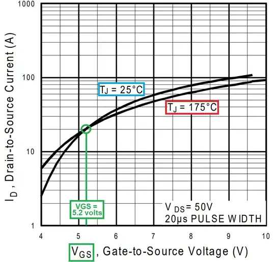
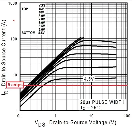
In the LTSpice schematics attached, I simply hooked them up in parallel to the input ports (24DC) and the simulation results look okay however after doing some research online and from some great comments to my past queries on this forum I've come to realise that MOSFET gate threshold differes even between the same models due to varying temperatures. I looked up for current balancing solution to ensure Ids on all MOSFETS is always the same but the only solution I've been able to find by far are some exotic current balancing modules from nexperia. I was wondering if I can achieve the same using basic passive/active components?
I am thinking of attached a termistor directly to chassis of each MOSFET and use Arduino to calibrate Vref for each MOSFET but I'm afraid the thermal feedback will be too slow and MOSFETs will smoke well before Arduino has change to adjust the Vref.
Edit 1:
Additional information :
The input reference V1 and V5 are analog inputs coming from same analog output pin of an arduino to set the current drain. Theoratically and even in the simulation, the single reference should keep all three MOSFETs balanced however other variables like junction temperature of each mosfet will change the gate voltage threshold leading to large current flowing from MOSFET/s running cooler then the rest.
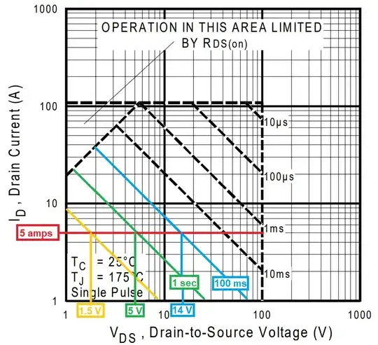
Although the schematic only shows 2 MOSFETs, I am looking for 3 MOSFETS to run in parallel with 5A max each making total Amp rating 15A. I am trying to understand how we can ensure the current through each one of these MOSFETs is equal at all time irrespective of their junction temperatures.
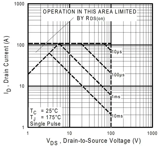
MOSFET Datasheet - https://www.farnell.com/datasheets/67691.pdf
