This thread is kind of case-in-point why I would like to discourage questions on EMC here; the format of this site is not well suited to topics of such complexity.
But as these questions inevitably continue, and as I inevitably draw myself into them... I ought to provide an in-depth explanation here.
I think it important readers understand why I say this. The Stack format is rigid: one question, few quick answers, upvote ranking. Only the most minimal peer review occurs by upvotes, comments, and rarely, edits (and flags to moderators in extreme cases). This format discourages complex topics, that either require considerable background information to cover meaningfully, or require ongoing conversation to sort out a user's confusions.
So, I'm engaging in writing this answer, knowing not just its length, but the delay introduced by disclaimers or meta like this, have the unfortunate effect of greatly reducing the readability, reviewability, popularity, whatever, of it. Still, I consider this a necessary sacrifice.
Newbies, probably, cannot conceive of just how complex and encompassing EMC topics are; this has certainly been my experience with the topic here (but, that's still only dozens of occasions, hardly a general sampling). But it's not limited to newbies; even among seasoned veterans, largely they work within only a limited subset of the entire topic. As a result, we often make incorrect extrapolations to work outside of that set. It is truly an exceptional case, when one works with such diversity of applications, often enough, and builds and maintains a deep understanding of them, that one can truly be considered an expert; these are very few indeed, and so we justifiably celebrate such authors as Henry Ott, who has literally written the book on Electromagnetic Compatibility Engineering.
In the interest of openness, disclosing bias, blind spots -- for my part, I mostly work with commercial designs. If you hand me a design to review, without any specifications, I will assume levels typical of say EN 55024 (unless it's patently obvious it should be something else). I would say I have a strong understanding of EM waves and fields, how they move around impedance networks (circuits, cables and systems), etc. I am proud to say I've brought over a dozen products through testing, with none or only minor changes required to the design (e.g. add ferrite bead here or there), that did not necessitate a re-test. (That includes cases where I made a major revision to an existing, failing design, which passed in one revision from me, obviously not counting revisions before I was involved.)
Anyway, to explain this topic, first: an introduction to testing.
EMC Testing
These tests won't, in general, be equivalent to real scenarios, especially if your exact scenario happens to be well defined (EUT installation, wiring situation, aggressors and victims all known); but they are designed broad enough that, anything which passes the set of tests, is likely to succeed in practice; and, anything that fails in practice, has a good chance of accusing the aggressor of fault (i.e. some other equipment is violating its emissions levels) rather than itself (susceptibility failure). And if nothing else, most equipment must simply tolerate impaired operation; unless you're willing to pay for it (i.e. something important, like life-support equipment), reliability simply doesn't (or shouldn't!) need to be so strict that momentary interruptions are unacceptable. Such is the basis of, for example, US FCC Part 15 compliance; the FCC recommends, but does not require, immunity testing, and devices simply must "tolerate" harmful emissions in their environment.
Definitions:
EUT (Equipment Under Test)
EMC (Electro-Magnetic Compatibility)
Conducted
RF energy is applied to the system directly, via coupling networks. A LISN (Line Impedance Stabilization Network) is used to couple directly to the mains port. Wired data pairs or other ancillary connections use a CDN (Coupling-Decoupling Network). Other cables use an injection clamp, including fixed cables between units of the EUT, if long enough (typically ≥3m).
Typical levels: 3V RMS (unmodulated), 80% AM (1kHz), 150kHz to 80MHz. Example method: IEC 61000-4-6.
Radiated
RF energy is applied to the system via radiation from an antenna, in a suitable (usually semi- or fully-anechoic) chamber. The EUT is set up in specified manner (elevated on a metal or insulating table, cables dressed, connections to ancillary equipment terminated with ISNs or CDNs, etc.). Both linear polarization directions are tested, and field strength is checked in front of the EUT.
These tests (conducted and radiated) simulate the effect of malfunctioning equipment (erroneous emissions) and nearby radio transmissions (presumably, licensed users: handheld devices, portable and fixed transmitters, radio towers, etc.). Spot checks can also be performed at specific frequencies, such as ISM bands (where higher emissions are permitted for unlicensed users).
Typical levels: 3V/m RMS (unmodulated), 80% AM (1kHz), 80 to 1000MHz. Example method: IEC 61000-4-3.
Electrical Fast Transients (EFT) and Electrostatic Discharge (ESD)
I'm lumping these together merely for their waveform similarities, and effects on the circuit; the actual test methods are actually quite different.
EFT is applied via coupling network or capacitive cable clamp. The waveform is, as the name suggests, a fast pulse: 5ns rise, 50ns width, 50Ω source impedance. This is fast enough that the wave energy physically "washes over" the system, at (near-)light speed, and reflections off cables and modules are visible on the oscilloscope trace. Because of the transient and cable-guided nature of this test, impedances remain comparable, and so we expect similar impedances where these waves crash into EUT interfaces, like logic pin clamping diodes (1kV / 50Ω = 20A, these are intense pulses; not for long, but it doesn't take much time at this power level to fry a microcircuit!).
ESD is a more practical, day-to-day sort of situation: sparks are applied to any exposed metal, any part of the surface where a spark can jump, and to coupling planes placed around the EUT such that the resulting EMP (Electro-Magnetic Pulse) can affect the EUT (emulating the effect of striking a metal table, a nearby filing cabinet, etc.). As the switching event is a spark in air, the rise time can be impressively fast: under a nanosecond. Needless to say, this wavefront washes over the system, radiating outward in space, carried upon wires and metal surfaces and bouncing off them. From my own testing, a slot type gap in an enclosure, subject to direct ESD in the middle of the slot, passes significant energy (enough to disrupt digital signaling on boards within the enclosure) for a slot length of just a couple inches -- that is, the slot looks like an inductive path, around which ESD current must flow, and some energy therefore can pass inside via this route. The peak current from direct contact can be over 30A, again a tremendous input for microcircuitry. And with many kV behind it, this is simply not something you can insulate away; it must be shunted around the circuit.
Pulse rate: ESD pulses tend to be single, infrequent events (1s+ between). EFT typically has a burst distribution, which emulates the discharge of inductive loads (solenoids, transformers, motors, etc.) across opening mechanical contacts. Typically the repeat rate is 5 or 100kHz, 75 pulses per burst, and 300ms burst repeat rate. This makes EFT uniquely capable of knocking out digital communications, for example by corrupting a packet, the subsequent retransmission packet, and so on. Robust error detection, correction and mitigation methods are therefore valuable additions to the protocol.
Typical test levels and methods: ESD: 4/8kV (contact/air discharge), IEC 61000-4-2; EFT: 0.5kV, IEC 61000-4-4.
Surge
Surge is a larger, slower waveform, used on applicable ports, typically long-distance connections such as mains power, and telecom cables, that are subject to induced or direct lightning surge, and transients due to inductive switching and line faulting. Typical rise times are a few µs, duration 10s µs to ms, peak voltages up to a few kV, and source impedances of a few to several tens of ohms.
Typical test levels: 8/20µs, 1.2/50µs "combined wave generator" (rise time / half-amplitude pulse width), 2Ω source impedance, 1kV differential (mains line-to-line), 2kV common mode (line to GND). Typical method: IEC 61000-4-5.
Among these tests, we can ignore surge to some extent, as the equipment is (presumably) isolated from hazardous mains voltage, and no other long-distance connection is specified. The power supply itself still needs to be tested for mains surge, but assuming it passes these tests (typically an off-the-shelf unit is chosen, carrying such ratings, among other useful features), no further consideration is required.
That leaves the fast-transient and modulated-CW tests to pass.
Equivalent Circuit
According to the description and comments (at time of writing), the system is composed of:
- A mains input connection
- One PCB containing an MCU and unstated other circuitry
- A cable to another board, carrying power, serial comm signals and unstated (logic level?) signals
- Another board with HMI elements, presumably another MCU to provide the HMI-to-serial interface, and an RF module (and perhaps the module provides the programmable MCU too).
Relays are mentioned, but it's not clear what purpose they serve, if any; certainly there is no need for isolated contacts when there are no other connections made to the board. If they are, in fact, connecting to switched mains circuits for example, that would be critical information, absent from the question, with likely major consequences for this analysis. I will assume for now that the relays connect to nothing, or only low voltages within the circuit, so can be ignored, as with other components within the local ground plane.
Given this description, we can create an approximate equivalent circuit for EMC purposes.
We will choose a LISN to represent the mains connection, and assume the system would be tested on elevated ground plane, thus giving a modest and consistent CM impedance for cables with respect to the plane, and some lumped-equivalent capacitance of the two modules with respect to the plane.
This might be drawn as follows:
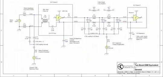 Source: own work; available on website: Two Board EMI Equivalent.png | Seven Transistor Labs
The input/mains filter is left as a skeleton, as only the broad strokes are relevant: some CM impedance provided by a CMC (this being the most common arrangement), and some isolation impedance provided by the transformer and a 'Y' type capacitor. The low-voltage supply is not shown, but implied between 3.3V1 and GND1.
All signals in the cable are not shown; only two, GND and TXD, are highlighted for purposes of simplification. Without loss of generality, similar circumstances can be applied to all. Note that, assuming VCC is bypassed at both ends, that wire acts in parallel with GND, providing a rudimentary shield around neighboring wires; this effect is implemented by the coupling factors K between the inductances.
Notice there are many assumptions here already, and many more simplifications. A ground plane has been assumed for both PCBs. This is a matter not just of convention, but fundamental sanity: without a plane, traces are subject to the free fields around them, and the whole analysis is sausage. That is, it would no longer be meaningful to speak in terms of supply or signal voltages, with respect to an implied reference ground plane; all voltages between any given points in the circuit, would depend upon the path of the measurement itself (in general, voltages between points in a field are dependent on the exact size and shape of the measurement loop). Put another way, the voltage measured between different points in the circuit, even those notionally equal (the GND net, the connected (galvanic) circuit between pins assigned as such). That is, there would be voltage, in general, between points within a given net, true for any net onboard.
It is possible to construct effective designs without planes, or with fewer than recommended layers; the challenge however increases exponentially, as one must account for both local and ambient fields swirling around all connections, and filtering RFI, clamping ESD, etc. all become far less well-defined -- and less effective.
Thus, the GND1 net, here, implies the whole ground plane of the PCB, and if you like, 3.3V1 is the supernode related thereto by adequate supply bypassing. Likewise for GND2 and 3.3V2 on the second board.
This leaves the point of interest, and the subject of the question: what to do with the cable between boards?
Immunity, Signaling, Filtering
Let us apply the various standards to the circuit as given:
Conducted: only the mains port applies. This is represented by V2. There are no other external connections to terminate or excite.
The equivalent circuit is of the system having some stray impedance to ground, which therefore draws some current from the conducted source (at the LISN), and consequently drops some voltage along the impedances between sections, particularly the between-boards cable.
The voltage drop along the cable, depends on the relative impedances around it, and its own. Note that a voltage drop between boards, is not an automatic failure: there is, however, some CM-DM mode conversion, which needs to be accounted for. That is, the current flowing on the GND/VCC wires, is not also flowing on the signal wires (as it would in a true differential circuit), and therefore not all the voltage drop (between boards) gets applied to the signal lines. This is evident in the equivalent circuit, for example because TDX1 has a resistive source impedance, and TXD2 a high load impedance (gate input pin), while the GNDs are hard-tied to both PCB planes.
Radiated: we can employ some hand-waving here. At lower frequencies, the linear structure of this system looks like a 1/4 wave antenna, common at the mains LISN, with two modest loading capacitors along its length. (Incidentally, the mains cable equivalent is not shown; we can roll it into L4's overall impedance, for the most part.) To the extent that L4's impedance dominates over cable impedance, we can also consider it a break in the line (in which case the two boards and comm cable look like an end-loaded resonator). The mechanism of coupling will be mutual inductance, primarily around the base of this structure (i.e. the mains cable); and mutual capacitance, primarily around the PCBs and connecting cable.
At high frequencies (wavelengths comparable to the cable electrical lengths), we cannot use a lumped-equivalent model to express the cables, and a transmission line model takes over. The mains cable equivalent remains a wildcard, as does L4 (typically, CMCs have falling impedance above a few MHz, but the impedance in the 10s or 100s of MHz may peak up or down erratically). We can at least note that the mains cable has a modest ballpark CM impedance (for a typical two-conductor cable elevated 50mm above the plane, this will be around 150Ω), and is terminated into a 25Ω LISN (both channels acting in parallel, V2 = 0), so should have a maximum Q factor around 150/25 = 6. Thus we do not expect mains cable resonances to be any stronger or peaker (narrow) than this factor.
The two-boards-and-cable structure acting as an end-loaded dipole resonator, manifests at frequencies where that structure represents about a half wavelength. Since the cable is 25cm, the wavelength will be around 50cm or 600MHz; this is something of an upper limit, whereas the two PCBs act as lumped capacitors against the cable's inductance, lowering resonance. I would guess somewhere in the 300-600MHz range, sensitivity is highest.
There will be subsequent peaks and valleys above this frequency, and also corresponding to dimensional scales such as the board length/widths, exact lay of the cables, trace or patch antenna modes on the PCBs themselves, etc.; but these will largely be at high enough frequencies we don't need to worry about them, at least at a first pass. (Depending on standards used, immunity beyond 1GHz may be required, perhaps even including harmonics of the radio module -- so, up to low 10s of GHz. These are such high frequencies that they aren't meaningful to consider in terms of conduction along cables, and whole-board shielding is basically the only effective mitigation. Boards are generally not very sensitive up here -- the attenuation between free fields and thin traces over ground plane, is pretty reasonable for commercial applications and test levels -- but if necessary, shielding of any sort, from absorbent materials, to metal cans, or milled enclosures, can be applied, depending on severity and budget.)
EFT and ESD: these are somewhat of a hybrid case, in terms of analysis; the edge rates are fast enough to consider the mains cable at least (well, most likely?), and EFT maybe not so much the connecting cable, but ESD most likely so, as transmission line equivalents rather than LC lumped equivalents.
Note that, because the connecting cable is less than 3m, it most likely does not need to be tested by itself with use of a capacitive clamp coupler. Thus, V3 = 0, and we only need consider direct mains-conducted transients, and ESD anywhere exposed metal can be struck.
Given the defined setting, we might still opt to set up a more detailed/specialized environment, mimicking the nearby mains wiring. We could, for example, set up a "dummy" cable, that is unpowered, terminated into ISNs at both ends, and excited with EFT from one or the other end (preferably, test both), and against which the EUT is positioned in a representative manner. Such testing will not be found in the most common, general standards, but can be constructed by agreement between a supplier and customer (typically only when such contracts constitute enough value to specify and test to such detail -- mains distribution switching equipment, and railway equipment, are two such examples that come to mind).
Given the impedances in circuit (largely the ratio of cable CM to DM mismatch), and the rapid rates of these waveforms, we expect considerable peak current and/or voltage to appear at the transmitter and receiver of these signal lines.
There is a strong advantage to the topology, however: because one board is "flapping in the breeze", its CM voltage can ride up to whatever at modest time scales (corresponding to frequencies ≪100MHz, say) without drawing excessive current in response to that voltage, as it would if it were hard grounded for example. As a result, these pulses are differentiated (high-passed), to some extent; the outcome is a strongly reduced energy dissipation required of the circuit, versus EFT or ESD being dumped hard into a pin directly.
The important take-aways here are the ratio of impedances, and the frequency ranges over which we expect concerns. At frequencies proportionally lower, we expect proportionally higher immunity (voltage or current). If due to cable/board resonance, we expect a tolerance of less than 1V (or 1V/m, roughly speaking) at 300-600MHz, we expect a tolerance of perhaps 10V at 30MHz, and so on. With a 3.3V logic level and 3V or 3V/m testing, this suggests we should only have problems at high frequencies.
Another take-away, that might not be so obvious from the above, but supports it greatly: only use the bandwidth you need! 9600 baud is a 104µs pulse time, which only needs as much analog bandwidth to convey; we might still maintain a good 30-100kHz analog bandwidth just to preserve a cleaner waveform. (This arises as a tradeoff between UART timing recovery, MCU pin input noise immunity (that is, the filtered analog signal with respect to the pin receiver itself), and how the UART samples the waveform -- typically three samples taken from the middle of a pulse, where a pulse is 8 or 16 sample periods long.)
The required 100kHz bandwidth, is hugely below the range of concern (10s MHz), making this a trivial slam-dunk strategy to ensure clean data.
Might it even be enough margin to pass EFT or even ESD without data corruption?
We can simulate these situations and take a look.
Simulation
For modeling purposes, I'm representing L4 as a 100Ω resistor. This is probably on the pessimistic side, but also doesn't capture any peaks or valleys a real part (plus the mains cable we're implicitly rolling into it) might have. Parts aren't documented to such frequencies anyway, nor are they consistent (the peaks and valleys vary from part to part, due to manufacturing tolerances), so this is a compromise solution.
I'm also changing the cable CM model, from capacitance to a reference plane, to a resistor from each capacitor pair (C1, C7; C2, C8; C3, C9) to ground. Let's say 10Ω each. This is a bit of an on-the-fly change, I apologize, but it is justified because we need some representation of radiation losses at these frequencies; meanwhile, there is no longer a need to illustrate the capacitive clamp.
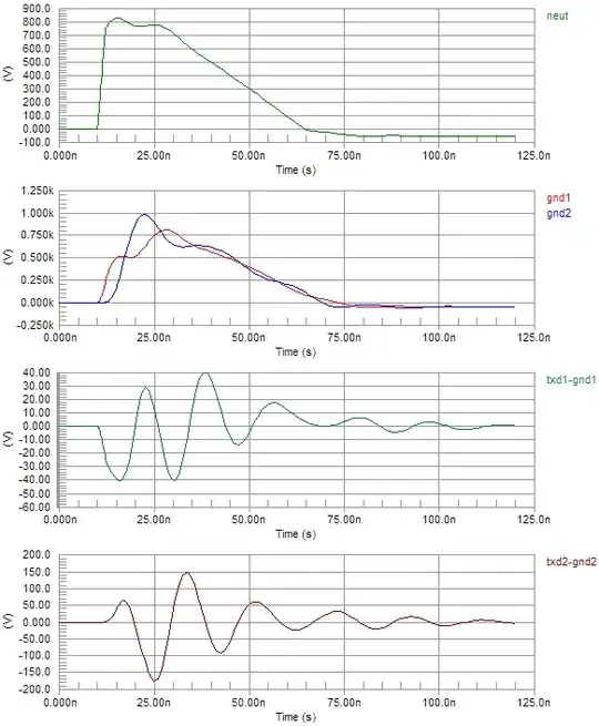
Without any load at the receiver side (an assumed linear open-circuit pin), the TXD2-GND2 voltage is about 170V:
Adding a BAV99 clamp diode and local 3.3V supply, a much more modest value results; notice the signal is disrupted for about a hundred nanoseconds, then returns to its intended (low) value. (Without loss of generality, the same will be true for a high state, at least within variance -- the pin driver's output impedance will be slightly higher most likely, that's about it.)
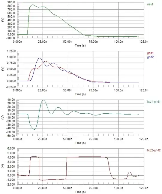
Mind, this is with R1 in place, implying a linear output resistance; in practice, the output pin driver will clamp to its body diodes, reducing the peak at TXD1-GND1. This doesn't have much effect on the result at TXD2.
Applying a 1k + 1nF RC filter, we get ample analog bandwidth (~160kHz), modest attenuation at HF (it's only a single-pole filter), and -- a completely clean signal:
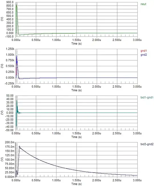
TXD3 is the added RC node (not shown on the above schematic, another running modification I apologize for). Peak is well below the typical CMOS input pin threshold of 30% VCC or 1V. This is at 1kV EFT (applied via NEUT); presumably this could be about five times worse or 5kV and still adequate, which brings us up to ESD levels (4/8kV), perhaps with moderate interruption of service (bit errors once in a while); a simple error detecting and re-transmitting protocol would seem adequate, or if it's a regularly-sampled HMI thing, you might simply not care that a packet is erroneous once in a while, thus delaying its reception by one sample period. (If you're transmitting only changes e.g. in LEDs or pushbuttons, you might want to use a CRC in the packet, followed by a simple ACK response or such, to ensure errors can be detected and packets retransmitted. Otherwise, continuously re-transmitting fixed levels, with a CRC or whatever to detect errors, should be simple and effective.)
As for AC response, this is approximately the conducted sweep. Albeit to much higher frequencies, for which a radiated model should apply.
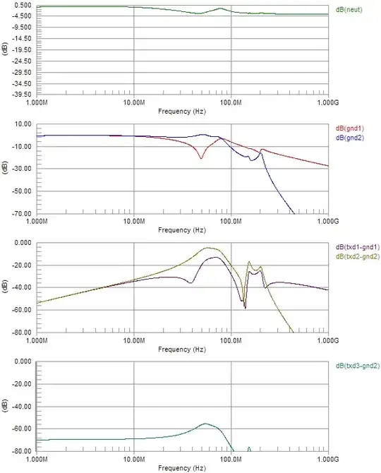
This is normalized to 0dB at NEUT input (not counting its self-impedance, hence the lumpy trace at top), and at least gives the jist of what to expect. Note the sensitivity due to CM-DM mode conversion competing with isolation capacitance, peaking around 50-60MHz; and the extra blips up around 150-200MHz, corresponding to cable resonances (evidently, the values I picked are a bit "long", modeling closer to a 1m length cable; this is all very approximate, just for show, not a real worked problem). Even accounting for other coupling methods (better representing a radiated mode), it's clear the attenuation to the receiver pin, with filtering, will be highly effective.
Other Signaling Standards
Notice that, to this point, I haven't even mentioned other signaling standards, like RS-232 or -422 (let alone protocols like CAN)! The noise margin of these is much wider, owing to higher voltage levels* or differential mode operation, and they can be used in conditions like these without filtering (at least for immunity purposes), while also offering capabilities like multi-drop, multi-master, bidirectional communication (half-duplex or time-division multiplex) on a single pair, etc.
*RS-232 is a funny one, because in its original embodiment, it might be 12, 15, even 20V or more at the transmitter's supply -- bipolar (±15V or whatever), so that the receiver could have a threshold near GND while offering a large noise margin (>10V) in either state. It's been diluted over the years (and, frankly, isn't very relevant anymore anyway; we're quite happy these days to use differential pairs, on more elaborate, robust and flexible networks, like CANbus for example), so that a MAX232 clone that operates on 3.3V, might only deliver ±6V output -- leaving a noise margin hardly higher than the logic-level signals driving it. It's still an improvement, granted -- and 6V is greater than 3V (or 3V/m, for hand-waving V/m ≈ V), so it's not like it's useless out of the gate. But in such typical modern use, it is merely a shadow of its former self. Anyway, not that it was ever widly flexible or anything: the pin states are fixed so you can't make a multi-drop bus, and the slew rate and output current are limited so that it can't go very fast (120kbps or so).
I haven't mentioned the media either, simply assuming the worst case (multiconductor cable, no shield/screen).
But we can apply similar analyses to these, and draw similar likely conclusions:
- RS-232 will pass conducted and radiated, and may fail transients without filtering
- RS-422/485 will pass conducted and radiated, and may fail transients without filtering
- Differential pairs require additional wires in the cable, adding cost
- Shielding (assuming adequate bonding to PCB grounds on both sides) can be used to assure, any of these really, will pass all tests
A cost analysis might justify the use of one or another kind of cable, or what interface to apply. For my part, I would be more than happy using ESD clamp diodes on both ends, a small source-termination resistor on the transmitter end, some RFI filtering at the transmitter, and an RC filter at the receiver end (maybe an RLC filter too, a ferrite bead on the line then a small cap at the clamp diodes to get more RFI immunity).
A similar filtering/protection scheme would be desirable for any signaling standard regardless; and obviously, differential will need more filter components. Granted that clamp diodes may be assumed provided with the interfaces, if their ESD ratings are adequate (8/15kV levels are often provided for robust automotive or industrial use), but this can be a dubious course of action as you need to know whether the devices will recover automatically from ESD strike, or require a power cycle to resume normal operation.
Note that it's not adequate to use oversimplified filtering schemes; for example, an RS-485 transceiver, in receive mode, filtered by only a common-mode choke (CMC), sees little if any attenuation of common-mode noise because its input impedance (small capacitance || high resistance) drops little voltage across the CMC. Some CM loading is necessary. For point-to-point links (such as this), the termination resistor can have its midpoint bypassed to GND, then offering excellent CM immunity. This is not permissible in multi-drop links, for which at most, some mild amount of capacitance can be introduced, and only as a significant compromise to baud rate and distance limits of the network. (A CMC does still offer transmit-mode CM filtering, which can be a strong benefit for emissions.)
Summary continues here: https://electronics.stackexchange.com/a/689139/311631


