I am trying to implement a circuit for searching for the largest eigenvalue and respective eigenvector of an operator, i.e. phase estimation, introduced in article Towards Pricing Financial Derivatives with an IBM Quantum Computer, page 6, figure 3(a).
The authors of the article use the phase estimation for indentification of the most important component in principal component analysis. In particular, they look for the largest eigenvalue of this matrix
\begin{equation} \rho= \begin{pmatrix} 0.6407 & 0.3288 \\ 0.3288 & 0.3593 \end{pmatrix} \end{equation}
The largest eigenvalue of the matrix is 0.8576 with respective eigenvector $(0.8347; 0.5508)^T$.
To search for that, the authors proposed following cicuit

Note that gates denoted by -1.57 and -0.79 are $S^\dagger$ and $T^\dagger$ respecitvelly. They act on "bottom" qubit and they are controlled by "top" qubit
$U3$ operators implement operator $\mathrm{e}^{2\pi i \rho}$ and its powers.
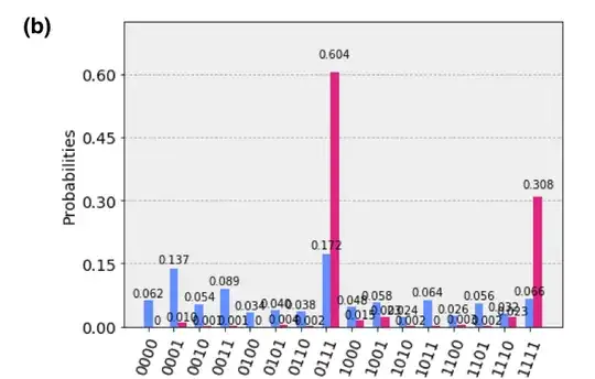
According to the article, results after measurement should be these:
Note that pink bars are results obtained on simulator, while blue ones on IBMQX2 processor.
Based on these results, the authors concluded that the largest eigenvalue is approximated by value $0.111_2$ (0.875 in decimal which is close to actual value 0.8576).
I tried to replicate their results with this circuit on IBM Q:
Note: please find a code in QASM at the end of the question to see parameters of gates
I received these results on IBM Q simulator.
According to my results, the largest eigenvalue should be zero which does not make sense.
So, my questions are these:
- Where I did a mistake in circuit implementation? My circuit and the author's seems to be the same.
- Why the qubit $|q_3\rangle$ is initialized by gates $Ry$ and $Rz$ with parameter $\theta$ equal to 1.00 and 0.33, respectively? I would expect only gate $Ry$ with $\theta = 1.1665$ as this gate produce the eigenvector $(0.8347; 0.5508)^T$. However, replacement of $Ry(1.00)$ and $Rz(0.33)$ with $Ry(1.1665)$ does not change resulting histogram significantly.
Here is a QASM code of my circuit
OPENQASM 2.0;
include "qelib1.inc";

qreg q[4];
creg c[4];

h q[0];
h q[1];
h q[2];
ry(1.00) q[3];
rz(0.33) q[3];
cu3(1.6,-1.12,2.03) q[2],q[3];
cu3(2.23,0.51,3.65) q[1],q[3];
cu3(0.8,-4.53,-1.39) q[0],q[3];
h q[0];
cu1(-pi/2) q[0],q[1];
cu1(-pi/4) q[0],q[2];
h q[1];
cu1(-pi/2) q[1],q[2];
h q[2];
measure q[3] -> c[3];
measure q[2] -> c[2];
measure q[1] -> c[1];
measure q[0] -> c[0];


