2

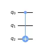
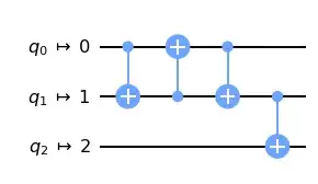
Here is an MWE: a simple circuit on three qubits with a CNOT acting on qubits 0 and 2. The coupling map prohibits a two-qubit gate between qubits 0 and 2 and so qubit 1 must get involved.

from qiskit import QuantumCircuit
from qiskit.compiler import transpile
from qiskit.transpiler import CouplingMap
from qiskit.quantum_info import Operator
from qiskit.circuit.library import Permutation

from itertools import permutations

qc = QuantumCircuit(3) qc.cx(0, 2)

coupling_map = CouplingMap([[0, 1], [1, 0], [1, 2], [2, 1]])

transpiled_qc = transpile(qc, basis_gates=['cx'], coupling_map=coupling_map)

Now, if I check

Operator(transpiled_qc).equiv(qc) # False

Although the resulting circuit looks reasonable

enter image description here

I thought that the difference between the original and the transpiled circuit might be a permutation of qubits, but the following check did not work either

for p in permutations([0, 1, 2]):
    permutted_qc = qc.compose(Permutation(3, p))
    print(Operator(transpiled_qc).equiv(permutted_qc)) # All False

Addition

If I fix the initial_layout in the transpilation options

transpiled_qc = transpile(qc, basis_gates=['cx'],
 coupling_map=coupling_map, initial_layout=[0, 1, 2])

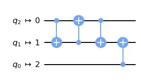
then the resulting circuit

enter image description here

is indeed equivalent to the transpiled circuit plus a permutation

permutted_qc = qc.compose(Permutation(3, [1, 0, 2]))
print(Operator(transpiled_qc).equiv(permutted_qc)) # True

My questions is now I guess -- how to be systematic about it? How to read out an appropriate permutation before trying all options (I have much more complicated circuits in mind). I mean, isn't it a basic human need to transpile a circuit and get True as a result of the equivalence test?
Martin Vesely
  • 15,244
  • 4
  • 32
  • 75
Nikita Nemkov
  • 1,725
  • 6
  • 22

2 Answers2

1

As noted in the comments by DaftWullie and me, the circuit is just missing a SWAP operation to return the qubit back to its original position... but this is not needed since your circuit only have one CNOT gate between the two end qubits. No other operations is being applied after the CNOT, hence you don't need to perform the SWAP again to return the qubit to its original position. If you do, however, you will see that both the circuit would have the same unitary matrix representation.

First, note that your original circuit is:

from qiskit import QuantumRegiste
qreg_q = QuantumRegister(3, 'q')
circuit = QuantumCircuit(qreg_q)
circuit.cx(qreg_q[0], qreg_q[2])
circuit.draw()

enter image description here

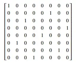
which has the unitary matrix representation of:

from qiskit.visualization.array import array_to_latex
from qiskit.quantum_info import Operator
array_to_latex(Operator(circuit))

enter image description here


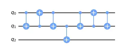
And if you consider the circuit:

qreg_q = QuantumRegister(3, 'q')
circuit = QuantumCircuit(qreg_q)
circuit.cx(qreg_q[0], qreg_q[1])
circuit.cx(qreg_q[1], qreg_q[0])
circuit.cx(qreg_q[0], qreg_q[1])
circuit.cx(qreg_q[1], qreg_q[2])
circuit.cx(qreg_q[0], qreg_q[1])
circuit.cx(qreg_q[1], qreg_q[0])
circuit.cx(qreg_q[0], qreg_q[1])
circuit.draw()

enter image description here

and if you look at its matrix representation, array_to_latex(Operator(circuit)), you will have:

enter image description here

which is the same as the one above.

KAJ226
  • 14,182
  • 2
  • 12
  • 34
0

When you transpile a circuit the addition of SWAP gates means that your two unitaries, original and transpiled, are related by a one-sided permutation matrix. This can be found by, for example,

op = Operator(qc)
t_op = Operator(transpiled_qc)

np.where((t_op.adjoint() & op).data == 1)

Paul Nation
  • 2,289
  • 9
  • 8