6

I am asking this question on behalf of user furious.neutrino. I asked this question at Electrical Engineering Stack Exchange, but it has not received a reply, so I am duplicating it here. I think the answer really requires someone who is familiar with both the physics diagrams below and in electrical schematics.

The question is how to translate the following diagrams from the language of physics into electrical schematics.

enter image description here

The diagrams come from this paper: Rajesh Gopakumar, From Free Fields to AdS, arXiv:hep-th/0308184.

The solid lines are easy to interpret in terms of electrical networks.

schematic

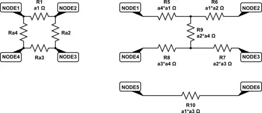
What I don't understand is how "the rest of the circuit" represented by the dotted lines are connected. In the left hand side, there are 4 terminals. In the right hand side, there are 6. Further, in the left hand physics diagram, are the dotted lines all connected? Or are they meant to cross without connection? That is, is the current in $k_1$ supposed to equal the current in $k_3$, and similarly for $k_2$ and $k_4$? Could someone complete "the rest of the circuit" for both diagrams?

Qmechanic
  • 220,844

1 Answers1

4
  1. The translation between Feynman diagrams and electrical networks in Ref. 1 is as follows: The Schwinger parameters $\alpha_i$ correspond to resistances $R_i$ while the momenta $k_i$ correspond to currents $I_{i-1,i}$, where $i\in\mathbb{Z}/4\mathbb{Z}$.

  2. On the electrical side the two equivalent circuits are depict in Figs. 1 & 2.

      x-----x-----[R2]-----x-----x 
      |     |              |     |
      |   [I12]          [I23]   |
      |     |              |     |
     [R1]   x--------------x    [R3]
      |     |              |     |
      |   [I41]          [I34]   |
      |     |              |     |
      x-----x-----[R4]-----x-----x 
    

    $\uparrow$ Fig.1. Original electrical circuit.

      x-----[R12]-----x-----[R23]-----x  
      |               |               |
    [I12]             |             [I23]
      |               |               |
      x-----[R13]-----|---------------x    
      |               |               |
    [I41]           [R24]           [I34]
      |               |               |
      x-----[R41]-----x-----[R34]-----x  
    

    $\uparrow$ Fig.2. Transformed electrical circuit. $R_{ij}=R_{ji}=\frac{R_iR_j}{\sum_{k=1}^4R_k}$, $i\!\neq\!j$.

  3. Figs. 1 & 2 are equivalent in the sense that the voltages $V_{i,i+1}$ across the current sources $I_{i,i+1}$ are the same for the two circuits whenever there is current conservation $$ \sum_{i=1}^4I_{i,i+1}~=~0$$ (with pertinent sign conventions).

  4. Note that this weaker notion of equivalence does not necessarily preserve potential differences between other nodes, which goes to the core of OP's question.

    Moreover, this notion of equivalence is invariant under reordering of components in series. E.g. if we exchange the positions of the resistor $R_{12}$ and the current source $I_{12}$ in Fig. 2. Similarly with $R_{23}$ and $I_{23}$, and so forth.

  5. Fig. 2 can be obtained from Fig. 1 by composition of 3 transformations, cf. Fig. 14:

    • Dual graph transform: Resistances become conductances, which are interpreted as a dual resistances $\breve{R}_i=1/R_i$. Current sources become voltage sources, etc.
    • Star-mesh transform$^1$: $\breve{R}_{ij}=\breve{R}_i\breve{R}_j\sum_{k=1}^4\breve{R}_k^{-1}$.
    • Dual graph transform: $R_{ij}=1/\breve{R}_{ij}$. Voltage sources become current sources, etc.

    enter image description here

    $\uparrow$ Fig.14 in Ref. 2. The original (transformed) electrical circuit is on the bottom left (right), respectively. Solid lines are resistors, while dashed lines are current sources.

References:

  1. R. Gopakumar, From Free Fields to AdS, arXiv:hep-th/0308184; p. 19 Fig. 4.

  2. E.A. Guillemin, Introductory circuit theory, 5th edition, 1958; p. 136 Fig. 14. An online version is available here.


$^1$ For $n$ terminals the star-mesh transform reads $$ R_{ij}~=~R_iR_j\sum_{k=1}^nR_k^{-1}\quad\Leftrightarrow\quad G_{ij}~=~\frac{G_iG_j}{\sum_{k=1}^nG_k},$$ where $G_{\cdot}=1/R_{\cdot}$ denotes conductance.

Sketched proof: Split nodes $\{1,\ldots,n\}=I\sqcup J$ in 2 non-empty subsets $I$ and $J$. Short-cut all nodes within a subset. Define $$ S_{IJ}~:=~\sum_{i\in I,j\in J}G_{ij}~=~\left(\frac{1}{\sum_{i\in I}G_i}+\frac{1}{\sum_{j\in J}G_j}\right)^{-1}~=~\frac{\sum_{i\in I}G_i\sum_{j\in J}G_j}{\sum_{k=1}^nG_k}$$ $$\quad\Downarrow\quad$$ $$ G_{ij}~=~\frac{S_{\{i\},\cdot}+S_{\{j\},\cdot}-S_{\{i,j\},\cdot}}{2}~=~\frac{G_iG_j}{\sum_{k=1}^nG_k}.$$ $\Box$

Qmechanic
  • 220,844