2

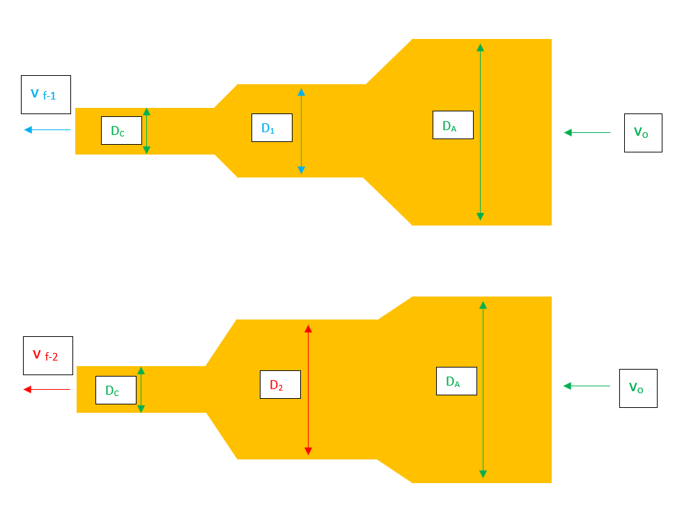
I do not frequently post on this community, so hopefully my question fits within the community guidelines. Below is a picture of two pipe systems. All values that are color coded in green are identical between the two pipe systems (e.g. $v_o$, the inflow velocity, in the upper system is equivalent to $v_o$ in the bottom system).

The primary parameters that I am interested in is how a change in the middle chamber's diameter ultimately affects the final velocity $v_f$ exiting the smallest chamber of the pipe system. For clarification, $D_1 \lt D_2$. I wanted to confirm that, correspondingly, $v_{f-1} \lt v_{f-2}$.

If this is correct, I would greatly appreciate any intuitive idea as to why this is the case. I assume it has something to do with the kinetic energy of fluid molecules in the top system being lower than the kinetic energy of the fluid molecules in the bottom system after transiting through the middle chamber (perhaps as a consequence of experiencing more total resistance during the passage through the pipe system).

In the event that any further assumptions are required to best answer this question, assume the following:

  1. the length of each chamber is the same between the two systems
  2. the length of the connecting pieces (i.e. the sloped transition sections) are the same between the two systems. However, these transition sections are obviously increasing their diameter at different rates (but I don't think this really affects the answer)
  3. gravity is either acting downwards OR right-to-left (but I don't think this really affects the answer)
  4. the fluid is water (so it can be assumed to be incompressible)

Thank you! Cheers~

Upstream Dilation

The following are orders of magnitude that the parameters referenced in the above picture will tend to float around:

  1. diameter $\lt 4$mm
  2. pressure $\lt 80$ mmHg
  3. velocity $\lt 20$ cm/sec
  4. Re $\lt 20$
S.C.
  • 188

3 Answers3

2

The Change $D_1<D_2$ causes the exit velocity to be lowered $v_{f-1} \lt v_{f-2}$ through higher velocity stack which simple means smaller effective $D_c$ for the flow.

This higher velocity stack is caused by the velocity difference $V_{D1}>V_{D2}$ It should be noticed that there is no possibility for velocity stack after $D_A$ because there is no "defining nozzle".

The maximum flow velocity (pressure is zero) is thus created on the entrance of $D_C$. This is the defining nozzle for the whole system, and all other velocities can be calculated through it. More information is avaible in this answer; Air core Vortex; Physical explanation of the "air Entrainment Hook" at $F_{co}=0.7$

Jokela
  • 2,517
1

Applying a mass balance to the entire system gives:

$$ D_0V_0=D_cV_c$$

where $V_c$ is the final velocity. So, the final velocity won't change if:

  1. You keep $D_0$, the middle diameter, and $D_c$ constant (i.e., the tube is rigid and can't deform).
  2. The fluid is incompressible.

Consider your real world example of the hose; if you step on the hose, the water is actually going to speed up to satisfy the mass balance. If you step on it enough, however, the water will slow down due to an appreciable change in viscous forces, affecting the momentum balance, requiring a larger pressure to pump. Your pump doesn't work harder to maintain new pressure drop that you just required, so the flow slows down.

Check out the momentum balance:

$$ \sum Forces= \rho A_cV_c^2-\rho A_0V_0^2$$ $$ P_0A_0-P_cA_c - F_{viscous}= \rho A_cV_c^2-\rho A_0V_0^2$$

and $F_{viscous}=A_s\tau_w$ is the pipe surface area times the shear stress at the wall (given from Hagen-Poiseuille flow in a circular pipe). If your pipe does not deform, however, I think that energy would then be dissipated and result in your fluid gaining thermal energy at the expense of kinetic energy. So yes, the final velocity should be lower in that case, but I don't know how to reconcile this with the mass balance. Maybe others can weigh in?

Thermodynamix
  • 1,802
  • 3
  • 19
  • 32
0

I think this is most helpfully framed as optimising the middle diameter.

The keys are to 1.Minimise the momentum change at the joins. 2.Realise that a horizontal pose will enhance vorticity and minimise momentum change angles and consequently energy loss.

As an optimisation it appears to be something like minimising the sum of the v.v.Sin(theta) of the two joins. As a rule of thumb I would guess that the optimal diameter squared is about midway, ie

D2=Dc✓DA/DC

Thereby weighting the minimisation to the primary loss at the small join. Vorticity is also likely to scale as V2, noting that gh is same order as V2 and the static pressure is significantly larger than the mass terms.

cumfy
  • 302