78

Why doesn't current pass through a resistance if there is another path without resistance? How does it know there is resistance on that path?

Some clarification:

  1. I understand that some current will flow through the resistance.
  2. A depiction of this phenomenon through Ohm's laws does not answer the 'why' part of the question as it does not illuminate the process behind this phenomenon.
  3. There seems to be disagreement among the answers on whether the charge repulsions are enough to cause this effect. Cited research would be appreciated to resolve this issue.
  4. To refine what I mean by this question, I think I should give an example of why I am curious as to the causal background of this phenomenon. If charge repulsions do in fact repel 'current' in the example of the short circuit, then why does the same phenomenon not happen in other parallel circuits. (Again, I know that not all circuits behave ideally)
  5. I believe the question is expressed in the most straightforward way possible. This should, however, not affect the scope of the answers. I do not wish to see or think on the level of an electron as circuit behavior always includes a cumulative effect due to the nature of electrostatic interactions.
ten1o
  • 1,255

20 Answers20

133

The basic circuit theory "rules" you imply, are high level simplifications applicable at a large scale and at slow speeds.

If you look at it close and fast enough, you could say that a current really starts to go into the obstructed path, but the electric field in front of the obstruction would build up gradually and current will start to repartition into the free path where it can start to flow. Naively you could say that the electric field will "sniff out" the paths. Actually in reality the current will also bounce off the obstructions, reflect and go back and forth etc. This is a real mess in practical electrical engineering at high frequencies.

BjornW
  • 7,217
47

I'll try to offer a simpler analogy of how that works.

Camp A on the side of a mountain is full of hikers. There is another empty campsite B on the other side of the mountain. And there are two possible paths between A and B - over the mountain or straight through a tunnel.

You order (apply voltage) the hikers (electrons) to go to camp B. While most are still packing, some hikers have their packs ready almost instantly and head out. A few of them go to the path leading to tunnel, a few go towards the mountain pass.

When the next batch is ready to go, once again few will go towards the tunnel and few will choose the mountain way. However, the latter group will get stuck as the previous mountain guys will be seriously slow trying to get up. So a queue will start to form.

When the next batch is ready to go, they will see that there is a queue on one of the paths and will (almost) all choose the easy way where none of the previous hikers got stuck.

Similarly, the electrons don't in some magical way feel that the path will be harder. They are simply stuck between a bunch of previous electrons that have hard time going that way so in the juncture they redirect to the route without the traffic jam.

The main difference between electrons in electrical paths and hikers on hiking paths is that all electrical paths are initially already full of electrons so the next electrons will instantly observe which path has trouble moving forward.

Džuris
  • 3,227
21

If there is a parallel path without resistance then the voltage across the terminals is zero. If the voltage is zero then, by Ohm’s law, the current through any branch with resistance is also zero.

Dale
  • 117,350
14

Why doesn't current pass through a resistance if there is another path without resistance?

Stipulate that there are two parallel connected resistors with resistance $R_1$ and $R_2$ respectively.

Since they are parallel connected, the current $I$ into the resistor network divides according to current division:

$$I_1 = I\frac{R_2}{R_1 + R_2}$$

$$I_2 = I\frac{R_1}{R_1 + R_2}$$

Now, let the resistance $R_2$ go to zero while holding $R_1$ fixed and see that, as $R_2$ gets smaller, the current through $R_1$ gets smaller and that, when $R_2 = 0$

$$I_1 = I \frac{0}{R_1 + 0} = 0$$

$$I_2 = I \frac{R_1}{R_1 + 0} = I$$

9

Current will flow through all possible paths no matter how high the resistance. The amount of current flowing through any given path will depend upon voltage and resistance. Given two parallel paths, one very high resistance and one very low, most of the current will flow through the low resistance path, but some will still flow through the high resistance path.

Even an electrical "short" will offer some small resistance. As current flows through a "short" there will still be a small voltage across it. So, if a high resistance is shorted and current flows through the short, there will be some small voltage across it, so some small amount of current will still flow through the high resistance.

In practical terms, we consider a short to pass all of the available current, but in truth, it is never all of the current; small, perhaps vanishingly and inconsequentially small amounts of current will still flow though other paths.

Anthony X
  • 3,666
7

Greatly simplified, let's say we have some electrons and two paths:

enter image description here

Now we apply electric field to them and they move:

enter image description here

The ones in the low resistance path have moved quite a distance, but the ones in the high resistance path didn't manage to move at all. Also a new electron has arrived at the junction and needs to make a decision.

The absence of electrons is a positively charged hole. So now Coulomb force acts on that new electron, and it is more likely to choose a low resistance path.

enter image description here

So there will be not enough charge carriers at the beginning of a low resistance path, and too many of them at the beginning of a high resistance path. It will cause charge carriers at the junction to prefer the low resistance path.

5

I'll give a partial answer because the real answer probably involves heavy math and is beyond my current knowledge. I wish a condensed matter or solid state physicist would take over and either demolish what I write or improve it.

I think most of the answers (not all) are wrong in that they assume that the electron-electron interaction is the responsible to prevent electrons to pass through a more resistive path than a less resistive path. This is wrong because the $e^--e^-$ interaction is "usually" negligible, and in any case do not account for the observed phenomena.

Instead I think the answer should come out of setting up a Boltzmann transport equation for the (quasi)electrons, considering the transient period of time. In other words, the density of electrons $f$ satisfy an equation of the type $\frac{df}{d t}=\frac{\partial f}{\partial t} \big|_{\text{scattering}} + \frac{\partial f}{\partial t} \big|_{\text{drift}} + \frac{\partial f}{\partial t} \big|_{\vec E \text{ field}}$.

$f$ depends on the position, time and is satisfied for each state $\vec k$. In the transient period of time, $\frac{df}{dt} \neq 0$, but after a short time, when the steady-state is reached, it is worth $0$.

To solve the equation and give an accurate answer, several assumptions have to be made. The first it to make clear whether we're dealing with a metal or a semiconductor. Then, some assumptions that reduces the range of validity of the analysis, such as making the relaxation time approximation that greatly simplifies the scattering (or collision) term. See the book of Ziman "Principles of the theory of solids", around page 215 for such a treatment.

An important and relevant point to note is that in metals, current is not due to slowly (drift velocity of order of $1\mathrm{cm}/\mathrm{s}$) moving electrons (this arises from the now obsolete Drude's model that many, many, many people still take way too seriously and would defend to death). Instead, current is mainly caused by the few electrons that have a speed near Fermi velocity.

So my current unfortunately not rigorous answer is that the electrons are taking all possible path they can, but the electrons responsible for the current (the few ones at speeds roughly equal to the Fermi speed) are getting scattered by impurities, grain boundaries, physical boundaries, phonons (and not so much with other electrons). This yields what we observe as resistance. So it is not that the electrons are avoiding the path with high resistances, it's that they do take it but they get affected in such a way that the resulting current is small. I emphasize once more: these electrons are few, move very fast (Fermi speed, i.e. about $10^6 \mathrm{m}/\mathrm{s}$ and for the most part, do not interact significantly with each other. Screening is a thing that many people here have forgotten.

4

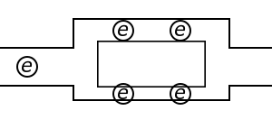
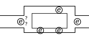
An electric charge will experience a force if an electric field is applied. If it is free to move, it will thus move contributing to a current. This is what the basic idea of 'Electric Currents in Conductors' is and this is apparently known to you. In nature, free charged particles do exist like in upper strata of atmosphere called the ionosphere. However, in atoms and molecules, the negatively charged electrons and the positively charged nuclei are bound to each other and are thus not free to move. Bulk matter is made up of many molecules a gram of water, for example, contains approximately $ 10^{22} $ molecules. These molecules are so closely packed that the electrons are no longer attached to individual nuclei. In some materials the electrons will still be bound, i.e., they will not accelerate even if an electric field is applied. In other materials, notably metals, according to the Drude-Lorentz Electron-sea theory, some electrons are practically free to move within the bulk material.

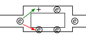
Resistance to electrical flow is due to the fact that when charge is given to a resistance, it remains stationary. In case of conductor, it is delocalised so it gets displaced and spread evenly on the surface, so note this carefully: in a conductor, charge flows mostly on the surface itself. This requires, undoubtedly some potential difference across the ends of the conductor but very less in magnitude. So, another fundamental rule/observation of universe is that "any dynamical process occurs in the path that requires least energy expense".

The most general and fundamental formula for Joule heating is: $$ {\displaystyle P=(V_{A}-V_{B})I} $$

where

$P$ is the power (energy per unit time) converted from electrical energy to thermal energy,

$I$ is the current travelling through the resistor or other element,

${\displaystyle V_{A}-V_{B}}$ is the voltage drop across the element.

The explanation of this formula (P=VI) is:

(Energy dissipated per unit time) = (energy dissipated per charge passing through resistor) × (charge passing through resistor per unit time)

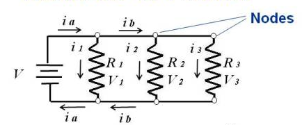
When Ohm's law is also applicable, the formula can be written in other equivalent forms: $${\displaystyle P=IV=I^{2}R=V^{2}/R}$$

When current varies, as it does in AC circuits,

$${\displaystyle P(t)=U(t)I(t)}$$

where $t$ is time and $P$ is the instantaneous power being converted from electrical energy to heat. Far more often, the average power is of more interest than the instantaneous power:

$${\displaystyle P_{avg}=U_{\text{rms}}I_{\text{rms}}=I_{\text{rms}}^{2}R=U_{\text{rms}}^{2}/R}$$

where "avg" denotes average (mean) over one or more cycles, and "rms" denotes root mean square.

These formulas are valid for an ideal resistor, with zero reactance. If the reactance is nonzero, the formulas are modified:$${\displaystyle P_{avg}=U_{\text{rms}}I_{\text{rms}}\cos \phi =I_{\text{rms}}^{2}\operatorname {Re} (Z)=U_{\text{rms}}^{2}\operatorname {Re} (Y^{*})}$$

where $\phi$ is the phase difference between current and voltage,$Re$ means real part, $Z$ is the complex impedance, and Y* is the complex conjugate of the admittance (equal to $1/Z*$).

So, this shows how energy inefficient is electric flow through a resistance under an applied potential.

4

This question has already been well answered, and in particular several of the correct answers referred to what you call "charge buildup" in the comments where you say:

The "charge buildup" theorem seems to be a point of disagreement among the many answers, while not much information exists on this concept anywhere else.

The "charge buildup" answers are correct and there is a lot of information in the literature about this concept. It should be noted that the "charge buildup" is called "surface charges" in the literature.

Perhaps the seminal paper on the topic is Jackson's "Surface charges on circuit wires and resistors play three roles". This paper describes how surface charges act "(1) to maintain the potential around the circuit, (2) to provide the electric field in the space outside the conductors, and (3) to assure the confined flow of current". In particular, your question is most focused on (3) with some overlap with (1).

Essentially, as others have said, at very short times the currents and the fields are not well-described by circuit theory. During that time the fields act to redistribute charges such that there is a non-uniform surface charge density which acts to provide the local forces needed to "steer" the steady-state currents into the patterns described by circuit theory.

Although Jackson's paper is the most famous on the topic, my favorite paper is Mueller's "A semiquantitative treatment of surface charges in DC circuits". That paper provides a method for graphically approximating the surface charge density in a rough semi-quantitative fashion. The graphical procedure helps build intuition for where surface charges will accumulate.

The basic idea is that the equipotential lines are continuous, including at the surface of a conductor, but they can have sharp bends at that surface. The angle of that sharp bend is proportional to the surface charge density. By graphically drawing equipotential lines and looking at how they bend at the surface you can determine the regions where there will be the greatest surface charge density. Specific hints are given for drawing the equipotential lines.

One other important concept mentioned Mueller's paper is the fact that inside a circuit, where you have a meeting of two conductors of different materials, you can get a surface charge. In other words, surface charges can occur inside a circuit where you have contact between the surfaces of two materials.

This specific type of "internal" surface charge is particularly important for your question since it is this type that prevents the charges from flowing through the higher resistance in your question. At the boundary between the highly conductive wire and the resistor there are surface charges which oppose any current flow into the resistor and effectively steer the current around. This is how the current "knows" where to go.

So, focusing on the resistor and specifically on the “interface” charges. Suppose initially that the current is too high (ie the current doesn’t “know” to avoid the resistor branch). This too-high current will lead to a depletion of positive charges from the entrance surface and an accumulation of positive charges at the exit surface. These surface charges will produce a field that opposes the current and reduces it. The charge will continue to accumulate until the current has been reduced to the steady state value.

Dale
  • 117,350
3

"Current flows through a path with no resistance" or "current flows through the path with least resistance" is a common misconception in electronics. In reality current flows though all paths, and the current in each path is proportional to that path's conductance.

If you apply a voltage V to a resistance R, the current I=V/R will flow through it, regardless of other available paths. In reality, you will have a hard time providing a path with strictly no resistance, or applying any significant voltage across a path those resistance is very low. In the end however, you will end up applying some voltage, at which point the Ohm's law will define the current in each path.

2

Okay, so we know that if a voltage is applied over a resistor with resistance R, then V/R amps with pass through the resistor. The problem is, what happens when R is zero? We have infinite current?

for the purposes of this example, assume that, when I say short circuit I mean "extrmely low resistance path." When I say infinite currrent, I mean extremely high current, and when I say no current, I mean basically no current.

Basically, yes. In a perfect world, if you shorted out a resistor that was connected to a perfect power supply, nothing would happen. The voltage across the perfect power supply (and therefore the resistor) would be unchanged, and a truly ludicrous amount of current would flow through the short circuit, while a normal amount of current would flow through the resistor. However, we do not live in a perfect world, and any real power supply will have a limited amount of current.

As the power supply loses its ability to supply the current the system is demanding (infinite), the voltage across the resistor will no longer be constant and will decrease to ~0. Since the voltage has dropped to zero, no current will pass through the resistor.

To put this another way, perhaps more clearly, there is no arbitrary rule that says a shorted resistor cannot have current pass through it, but the voltage across a resistor is proportional to the current, and the voltage across a short circuit is defined to be zero. Trying to apply a voltage to a short circuit will do nothing, it will simply short out whatever it touches.

Sam Spade
  • 272
2

Let's assume that the resistor and the wire around the resistor are part of a circuit with a battery and a switch.

Before the switch is closed, all battery voltage drops on the switch and all electric field is concentrated between the terminals of the switch, i.e., there is no electric field anywhere else in the circuit. The field across the switch is created by opposite charges on the switch terminals, which represent a small capacitor.

So, when the switch is closed, the initial voltage across the resistor is zero. As the the capacitance of the closed switch is discharged, the voltage and electric field across the switch decrease, while the voltage and electric field across the rest of the circuit increase, causing the current to flow.

Given a uniform initial field distribution, the current will flow faster where the resistance is smaller and slower where the resistance is greater. As a result, there will be a build-ups of opposite charges around the sections of the circuit with high resistance. This build-ups will cause redistribution of the initially uniform field, so that the field is concentrated in the sections with higher resistance, which will speed up the current through those sections, equalizing it with the current through the sections with low resistance.

Since the resistor in question has the low resistance path around it, there won't be any significant charge build-up and no significant field or voltage across the resistor, so the current through the resistor, according the Ohm's law, will be small in comparison with the current through the wire around it.

In summary, the current does not flow through the resistor with an alternative low resistance path, because there is no voltage across the resistor to push it through.

V.F.
  • 12,353
2

Charge build-up is not needed for the explanation of the phenomenon. The easiest way to understand why current "chooses" the path of least resistance is to stop thinking of current "choosing" anything, and think rather about electric field as a cause of all currents.

Two wires, connected in parallel to each other, have the same voltages drop. Assuming for simplicity the wires are of the same length and cross-section, same voltages imply same electric fields inside the wires. Same electric field causes more current in the low-resistance wire and since currents from both wires add up, most of the current will be coming from the wire with the least resistance.

$\textbf{PS}$. The language of "current choosing the path of least resistance" comes from the view of physics through Lagrangian formalism. The phrase is similar to "light chooses the shortest optical path" or "objects choose the least action path". One can demonstrate that if the total current through a system of resistors is fixed, the current distributes in a way to minimize the total power (sum of $P=I^2 R$) generated in the network. And since power is proportional to resistance, the current will "prefer" to go through the least resistance.

Pavlo. B.
  • 2,605
1

Let's suppose that a single battery is connected with a wire, which does not have resistance. Electrons will start to flow , in reality, with a wire with resistance, a potential difference would be generated across it. The current would build up until the potential difference is equal to the voltage of the battery. In the case in which potential difference is not created by the wire because there is no resistivity, the potential difference across will immediately become equal to that of the battery.

ten1o
  • 1,255
1

The present statement of the OP's question(s) is (are):

Why doesn't current pass through a resistance if there is another path without resistance? How does it know there is resistance on that path?

The short answers are:

  • Why: Current DOES flow through a resistance EVEN IF there is a path of lower resistance present, albeit this current may be miniscule compared to the main current. Nearly all materials at room temperature have a finite resistance hence will allow some charge to flow whenever an external voltage is applied across that material.
  • How: The very same mechanism that allows more current to flow through a lower resistance. In terms appropriate for electrical circuits, that would be Ohm's Law

$$V=I R$$

where

$$\begin{align} V & = \text{the applied voltage} \\ I & = \text{the current through the material} \\ R & = \text{the resistance of that material to the flow of current} \\ \end{align} $$

the derivation/justification of which I would consider beyond the scope of the current question. We simply note that nearly all materials exhibit this linear response to an applied voltage.

A simple circuit will suffice to illustrate these points. Consider the circuit consisting of three resisters wired in parallel:

Resisters in parallel

Conservation of charge says that the current that leaves the battery's positive terminal, $i_a$, must return to the battery's negative terminal. This current will be split into three different paths through the circuit (due to the physical construction of the circuit); some of it must go through resistor $R_1$ (labeled as $i_1$), some through resister $R_2$ (labeled as $i_2$), and some through resistor $R_3$ (labeled as $i_3$). Once again, conservation of charge mandates that what flows into a node ($i_a$ from the battery) must equal the sum of current flows leaving that node (sum of $i_1$, $i_2$ and $i_3$):

$$i_a=i_1+i_2+i_3$$

Solving Ohm's Law for the current through each resistor we find

$$\begin{align} i_1 & = \frac{V}{R_1} \\ i_2 & = \frac{V}{R_2} \\ i_3 & = \frac{V}{R_3} \\ \end{align} $$ so that $$ i_a = V \Big(\frac{1}{R_1} + \frac{1}{R_2} + \frac{1}{R_3} \Big) $$ where we have used the fact the battery voltage $V$ is applied to each resistor. Remember that $i_a$ is the total current provided by the battery, hence a single, equivalent resister of value $R_e$ would draw the same current from the battery if its value was given by $$R_e = \frac{V}{i_a}$$ Combining these last two expressions we find $$\frac1{R_e} = \frac1{R_1} + \frac1{R_2} + \frac1{R_3}$$ which is nothing more that the classic solution for the equivalent resistance of resistors connected in parallel.

To demonstrate how this result applies to the present question, let's assign some values to the battery voltage and resistors. Let

$$\begin{align} V &= 1 \text{ volt} \\ R_1 &= 1 \, \Omega \\ R_2 &= 1 \times 10^3 \, \Omega \\ R_3 &= 1 \times 10^6 \, \Omega \\ \end{align}$$

With these values we find the equivalent resistance to be

$$R_e = \Big( \frac11 + \frac1{1000} + \frac1{1000000} \Big)^{-1} = 1.001001^{-1} = 0.999000 \; \Omega$$

so that the current supplied by the battery is

$$i_a = \frac{1\;\text{Volt}}{0.999000\;\Omega} = 1.001001 \; \text{Amp}$$

The circuit then routes this current through the three resisters as follows:

$$\begin{align} i_1 &= \frac{V}{R_1} = \frac{1\;\text{Volt}}{1\;\Omega} = 1 \; \text{Amp} \\ i_2 &= \frac{V}{R_2} = \frac{1\;\text{Volt}}{1000\;\Omega} = 0.001 \; \text{Amp} \\ i_3 &= \frac{V}{R_3} = \frac{1\;\text{Volt}}{1000000\;\Omega} = 0.000001 \; \text{Amp} \\ \end{align}$$

Note that these three currents sum up to the current supplied by the battery:

$$ i_1 + i_2 + i_3 = 1 \; \text{Amp} + 0.001\; \text{Amp} + 0.000001\; \text{Amp} = i_c = 1.001001\; \text{Amp} $$

We see immediately that not all of the current followed the path of least resistance as $i_2$ and $i_3$ are not zero! The current simply followed every path that was possible.

Stated again another way, the current does not choose to take any particular path, it simply takes every possible path, period.

OneMug
  • 301
1

Basically electrons pass slowly through a resistor so it causes an accumulation of electrons in the resistor which then repel further electrons redirecting them into the other resistance free path.

Möbius
  • 606
1

The question is a bit misleading because it assumes that there is a « all or nothing » answer.

The correct question is:

« If you have two resistances in parallel, with values R1 and R2, what relative fraction of the the current will flow through R1 and R2, respectively? »

The answer is :

I2 / I1 = R1 / R2

So, basically, if R2 is a lot smaller than R1, if will drain most of the current away from R1 when a potential V is applied to R1 and R2 (but not all of it).

Serge Hulne
  • 1,744
0

Current will flow through all feasible wires, regardless of the resistance's status, so it will never stop. The amount of current flowing through will depend upon voltage and resistance. Given two parallel paths, one containing very high resistance and one very low, most of the current will flow through the low resistance path, but some will still flow through the high resistance path, regardless.

Always remember, little or small doesn't mean none at all. Even an electrically short resistance wire will offer a miniscule amount of resistance. As current flows through a shortage there will still be a small voltage across it. So, if a high resistance is shorted and current flows through the short, there will be some small voltage across it, so some small amount of current will still flow through the high resistance.

In short, we consider a short resistance wire to pass all of the available current, but in truth, it is not all of the current; small amounts of current will still come out via other paths.

Hopefully this was helpful in answering your question, @ten1o!

0

Your question appears to contain an erroneous assumption. Assuming a constant voltage, the amount of current that flows through a resistor does not depend on whether there are other paths in parallel. Electrons flow through all of the available paths, each independently according to Ohm's law.

Consider, by analogy, a hopper full of grain, at the bottom of which there are several openings of various sizes. The hopper will gradually empty as the grain falls out of the openings. The flow of grain through the larger openings will be greater than the flow through the smaller ones.

An individual grain in the hopper does not 'know' which opening is larger than any other. It simply moves down the hopper under the influence of gravity and the chaotic effect of innumerable collisions with other grains around it. In effect, it falls as the grains below it move and open up space for it to fall into. Since grains pass through the larger openings more readily, the regions above the larger openings contain more space into which other grains can move under the influence of gravity.

The conditions in a conductor that branches into a number of paths is similar. Huge numbers of electrons are mobile in the conductor. Any single electron is subject to an overall field that creates an overall drift and innumerable repulsive interactions with other electrons. The individual electron simply moves where it is forced by the combined effect of all these influences. On average, more electrons end up moving to the paths of greater conductivity because the electrons ahead of them are effectively moving out of their way more rapidly.

-1

I think conceiving of it as the current choosing to flow along the path of lesser resistance rather than the path of greater resistance is a misleading & complicating way of conceiving of it. If a resistor of such & such a value is placed across a source of EMF a certain current given by V/R will flow. If a different resistor is placed across the EMF, a different current will flow. If both the resistors are placed across the EMF simultaneously, then each resistor will simply conduct the current it would have done had the other been absent.

This argument assumes a perfect EMF source for simplicity; but it doesn't matter, because the effect of the being real rather than theoretically perfect of the EMF source is that the voltage across the resistors will fall slightly; but the situation is exactly the same as were you simply considering a perfect EMF source at the new lower voltage.

If the total resistance loading the real EMF source is very much less than it's internal resistance, to the degree that the source is supplying very nearly its closed-circuit current, then the voltage across the parallel load resistors will be a tiny fraction of the source's open-circuit voltage; but it's still the same as were you considering a perfect EMF source at _that _ tiny voltage: each resistor has the current flowing through it that it would have were it alone, at that voltage.