Let's say that I have a motor that's spinning really fast. I really want to know the angular speed of the motor. Using a stopclock definitely won't work as no one can time such fast rotations. So how would I find the rotational frequency in such a case?
Asked
Active
Viewed 1.5k times
10 Answers
49
There's a very interesting way to find the angular velocity of a wheel that's spinning so fast that you can't measure using a stopclock. We'll be using a strobe light (a light that flashes on and off repeatedly) and a very interesting concept known as the Wagon Wheel effect under stroboscopic conditions.
A little bit about the concept:
The Wagon Wheel effect is a phenomenon in which a spinning wheel may appear to be stationary under a strobe light. The reason why this happens is quite simple, the rotational frequency of the spinning wheel is an integral multiple of the the strobe light's on-and-off frequency. As a result, every time the strobe light flashes, the wheel comes to the same position as before. This creates the illusion that the wheel was stationary.
But how will we use this concept to find the rpm of a spinning wheel? Let's find out.
The experiment:
You'll only need a strobe light (you can download strobe light apps for Android and probably for iOS as well) and your spinning wheel. In this answer, I'll be using a fidget spinner to demonstrate.

Keep the room as dark as possible, and set your wheel to motion. Turn on the strobe light and start with a high flash frequency and gradually lower the frequency until you see the wheel become stationary. We do this because don't want other integral multiples of the frequency to match up with the spinning wheel.
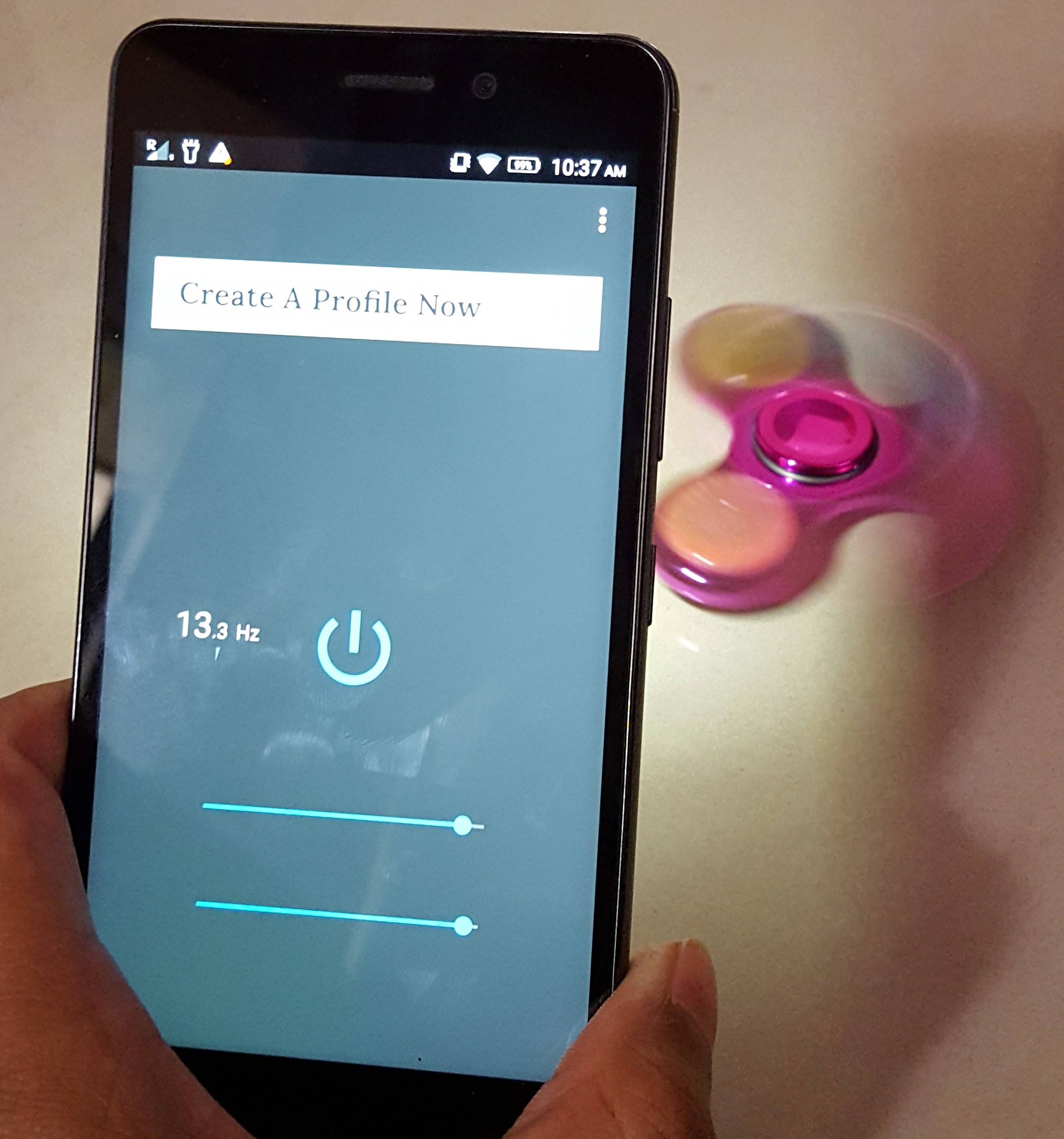
Take a note of the strobe light frequency $\nu$. In my case, the fidget spinner appears stationary at a frequency of 13.3 Hz. As we mentioned before, the wheel appears stationary only when the frequencies match. So, the frequency of the strobe light is the rotational frequency of the wheel. So, I can say that my fidget spinner makes 13.3 revolutions per second. And of course, it's rpm would be 798.
I hope you enjoyed this fun experiment. If you have any queries, please drop them at the comments. If you have a better way to find the angular velocity, don't hesitate to write an answer.
Pritt Balagopal
- 3,237
26
A laser tachometer:
https://www.amazon.com/Neiko-20713A-Digital-Tachometer-Non-contact/dp/B000I5LDVC
Make a mark at one point on the motor, then set it spinning. Point the tachometer at it. By shining a laser on the surface and measuring the changes in returned light as the mark passes, it can determine the RPM.
24
One idea for an approach may be to record the sound the motor produces and then Fourier transform that signal. The assumption is that the frequency you look for will be prominently visible in the spectrum of that signal. Of course, it is not clear whether this frequency is as easily identifiable as it sounds.
Gregor Michalicek
- 1,198
- 8
- 11
22
Print out a disk that looks like this:
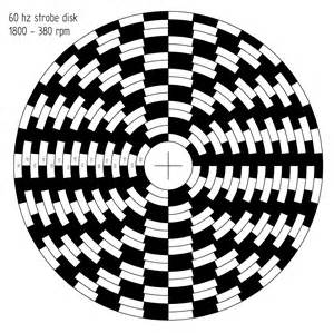
Attach it to the spinning object and then observe it with a 60 Hz strobe light. By determining which rings look like they are stopped by a 60 Hz strobe you can deduce the RPM of the object.
As you can see, the inner ring has 8 segments (4 white, 4 black), the next ring has 10 segments etc. If you rotate the disk by 90 degrees, the pattern on the inner ring won't have shifted. If you rotate the disk by 72 degrees, the pattern on the next ring won't have shifted. So, with a 60 Hz strobe, you can find which ring appears to be stationary. Call the number of segments in that ring N, then the disk must have moved 720/N degrees in 1/60th of a second. that's 2/N revolutions in 1/60'th of a second, so 7200/N RPM.
Do a web search for "printable strobe RPM" for more details.
MSalters
- 5,649
Eric Lippert
- 1,549
10
I happen to have done this exact experiment over the weekend - detailed write-up below. Basically it involved a laser pointer, a photo diode, two resistors, a transistor, and an Arduino. Set the Arduino timer to run at 10 kHz, and the output of the photodiode (into the interrupt input of the Arduino) triggers a "read" of the timer. When at least a second has elapsed, you print the ratio, reset the counters, and start again. Works really well over large range of RPM. I actually used it to measure the spindown of a fidget spinner - to demonstrate that the process is nonlinear, which proves that air drag plays a role.
Here is a picture of the "setup" (on the messy desk in my "den"):
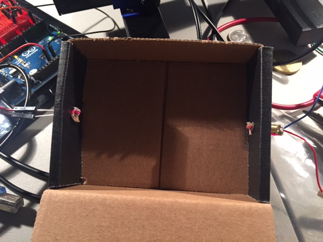
A simple cardboard box was holding a photo diode on the left (20 pieces for \$4.99 on Amazon *), and a small laser diode on the right (10 for \$6.99 on Amazon). I could hold a rotating fidget spinner in the beam, and the Arduino would do the rest.
And a scope trace of the signal: (a bit blurry - the scale is 20 ms per division, so there are about 30 interruptions per second as I took the picture)
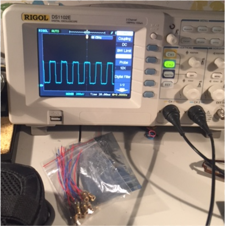
Obviously it helps to have a scope to set something like this up properly - but if you have a laser pointer that is pointed at your photo diode, and a way to interrupt the beam properly as the wheel rotates, you have quite a lot of leeway.
UPDATE
Here is the Arduino code I used to create the RPM meter:
// code to create an RPM meter based on an interrupted optical beam
long time=0;        // time since last measurement
long clicks=0;      // optical interruptions since last measurement
long totaltime = 0; // total elapsed time since reset

void setup() {
  // configure pin 2 for input:
  pinMode(2, INPUT_PULLUP);
  attachInterrupt(0, reportTime, FALLING);

  // setup timer:
  cli();//stop interrupts

  // set timer1 interrupt at 10 kHz
  TCCR1A = 0; // set entire TCCR1A register to 0
  TCCR1B = 0; // same for TCCR1B
  TCNT1  = 0; //initialize counter value to 0;
  // set timer count for 10 khz increments
  OCR1A = 199;// = (16*10^6) / (10000*8) - 1
  // turn on CTC mode
  TCCR1B |= (1 << WGM12);
  // Set CS11 bit for 8 prescaler
  TCCR1B |= (1 << CS11);
  // enable timer compare interrupt
  TIMSK1 |= (1 << OCIE1A);

  sei();//allow interrupts
  //END TIMER SETUP

  // turn on serial port at 9600 baud:
  Serial.begin(9600);
}

void loop() {
// nothing here - everything is interrupts
}

void reportTime() {
  clicks++;
  if (time > 10000) {
    // at least a full second has passed
    totaltime += time;
    Serial.print(totaltime);
    Serial.print("\t:\t");
    Serial.print(600000*clicks/float(time));
    Serial.write(" rpm \r\n");
    time = 0;
    clicks=0;
  }
}

ISR(TIMER1_COMPA_vect) {
  // Interrupt at freq of 10 kHz
  time++;
}
The circuit diagram is super simple. I attached a 5 V supply to the laser diode module (which has its own internal current regulator); it's possible it could run off the Arduino 5 V (it only takes 10 mA) but I didn't try that. The optical pickup was done with this circuit:
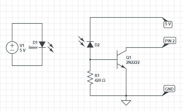
When the diode is illuminated, the current is split between R1 and the base of the transistor. Once the voltage across R1 reaches 0.6 volts, the transistor will "turn on" and pull current from the collector. This pulls down the signal that is connected to pin 2 (using the internal pullup of the Arduino). When the beam is interrupted, the current is reduced and the transistor turns off. Turning "on" (pulling down) is much faster than turning "off" with this circuit, so we trigger off the falling edge. You can make the circuit more sensitive by increasing R1 - the bigger it is, the smaller the light level needed to trigger. But it also becomes more sensitive to ambient light, and response is slower. With the laser diode, I found that 420 Ohm was a good value: fast response, insensitive to ambient light. But that's definitely a value to play with.
I tested the circuit at frequencies up to 1 MHz (driving the laser with a signal generator with a square wave), and it was fine - so the response time is well below 1 us. This should make it fast enough for many applications.
An example of using this to measure the RPM of a fidget spinner:
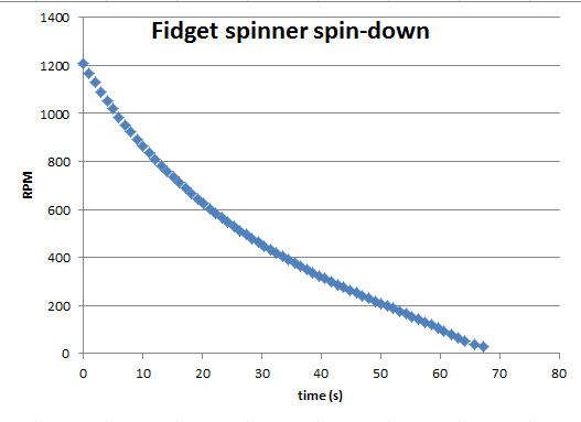
There are 3 interruptions per revolution on the spinner - and I have no problem measuring 1200 rpm (3600 interruptions per minute = 60 per second). Driving the laser with a signal generator, I was able to go much faster... up to 30 kHz. At that point, there is some overflow in the program and the numbers are nonsense (I suspect that the Arduino isn't fast enough to deal with 10,000 clock interrupts and 30,000 optical interrupts; some changes to the scaling might extend the range, but you won't need that for most purposes).
Running the laser at 1 kHz, I was seeing 59988 rpm - that is obviously "60,000" with some numerical rounding error (or the clock on the Arduino is not exactly 16 MHz, or...), so that is good. When you push the circuit too hard, interrupts will be getting in each other's way. The highest "correct" reading I obtained was with 3 kHz input, 179904 rpm output. That should be good enough for most applications... Even a bike wheel (with 32 spokes) going 100 revolutions per second (approx 2/3 of the speed of sound) could be timed with this. Of course the wheel would tear apart long before it reached that speed...
* I am not affiliated with Amazon or the companies making these components; just wanted to make it easy for you to find such parts
Floris
- 119,981
8
Attach your motor to a reduction gearbox. Measure the angular speed of the output and multiply by the reduction ratio to get the original angular speed.
Note that people are currently 3-d printing 11 million:1 or billions:1 reduction gearboxes. Example. Also, the output of a gearbox can be the input to the next one (although one should be aware of frictional losses and minimal required torque), so ridiculously fast motor angular speed can be reduced to essentially stationary output.
Eric Towers
- 1,797
4
Attach a DC motor, and measure its EMF, by plotting the voltage you measure at the connections you would typically supply the DC motor, had you used it as a motor.
Most simple DC motors have 3 coils, so on an oscilloscope you will see something similar to the absolute of a sine, where three such "hills" will correspond to one full revolution.
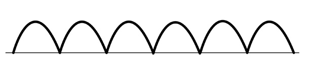
It is probably much simpler to install than a gearbox, and you will have much less trouble with friction especially if the speed is really fast.
vsz
- 1,099
3
My first attempt would be a slow motion video on my smartphone, count the revolutions for 10 seconds and times it by 6 to get an idea). The framerates could be too low for you though. (There's a new Sony smartphone with a 1000 frames per second drool, that's like 60,000 frames per minute. The Samsung S5's has 120fps.).
user3035260
- 41
1
My take on this question is based on this video. The idea behind this is that if you manage to transfer the angular velocity from the motor to a spinning disk and create the setup from the video, you can, based on the geometry of the setup and the precession velocity, calculate the angular velocity of the motor.
The calculation can be found here, pages 4-6, problem W14D3-2 Table Problem Suspended Gyroscope Solution. At the end of the problem you have the following formula where all the parameters are defined in the document:
$$\Omega=\frac{d\cdot m\cdot g}{I_{cm}\omega_s}$$
For your scenario, you can use the above formula, but to compute $\omega_s$ by measuring $\Omega$.
I hope this adds a different perspective to the problem than what was suggested so far.
Victor Palea
- 792
0
As seen, there are dozens of experiments that might help you, but a more simple and fairly accurate way can be by attaching a very small light at any random point of the wheel and turn it on. Then you can spin the wheel at your desired rpm and attach a sort of a light sensor of a high intensity (equal to the small light attached on your wheel). Then the sensor can count, in how much time the light of given intensity was detected, you can modify it such that every time a light beam of given intensity is detected, the sensor would mark it with a beep, and count the total number of beeps.
rigel_13
- 1,377