3

I am having problems to determine the direction of the induced EMF in AC circuits. For example, we have an inductor of inductance $L$. The induced EMF is given by:

$$ \epsilon = - L \frac{di}{dt} $$

where the minus sign is "explained" by the Lenz law. But how do I apply this to an AC current. The direction of current is changing (usually by sine or cosine laws). See the following link:

http://en.wikipedia.org/wiki/RLC_circuit#Series_RLC_circuit

for a series LCR circuit. Here the equation is given by

$$ L \frac{di}{dt} + Ri + \frac{1}{c}q = \epsilon_0 \sin (\omega t) $$

How do I know the sign of the first term on the left hand side... ? Why isn't it for example:

$$ - L \frac{di}{dt} + Ri + \frac{1}{c}q = \epsilon_0 \sin (\omega t) $$

When is it + and when -... Furthermore, how do I know the sign of any of the terms? The current is changing periodically. Why can't it be:

$$ L \frac{di}{dt} + Ri + \frac{1}{c}q = - \epsilon_0 \sin (\omega t) $$

My initial guess is that this depends on the point in time that we choose, but that ultimately gives us different solutions...
Qmechanic
  • 220,844

3 Answers3

4

I'm telling you... when I apply the laws I get the wrong equation... Why do we ignore the minus sign in front of L(di/dt)?????

The voltage across an (ideal) inductor is given by

$$v_L = L \frac{di_L}{dt}$$

(here, I assume the passive sign convention). The inductor emf has the opposite sign of the voltage across and, for solving circuits, we're interested in the voltage across. It's not that we're ignoring the minus sign, it's that the voltage across doesn't have a minus sign.

Consider an (ideal) voltage source, with non-zero constant voltage $V_S$, connected across an inductor. The voltage across the inductor is fixed by the voltage source. If there were no (induced) emf, the current would be arbitrarily large ('infinite') since the ideal inductor has zero resistance.

For the current to be finite, there must be an emf that 'opposes' the voltage $V_S$. Since, for a constant current through, there is zero emf, it follows that if the current is finite, it must be changing at just the rate required to produce an induced emf that is equal in magnitude to $V_S$.

$$\mathcal{E} = -V_S = -L\frac{di_L}{dt}$$

0

emf induced by inductor is negative but emf applied by battery on inductor is positive. So, that inductor tries net voltage across it is 0. Emf applied by battery is E°sinwt of which LdI/dt is applied across inductor, RI across resistance and Q/C across capacitor.

-LdI/dt is induced across inductor and not applied.

Now, consider direction of emf is changed and emf now is -E°sinwt. Now voltage across resistance, inductor and capacitor also become negative. $$ -E°sinwt = -LdI/DT - RI -Q/C$$ = $$E°sinwt = LdI/DT + RI + Q/C$$

Anubhav Goel
  • 2,130
0

This is a very interesting question which has at least two answers.

The first answer is for an electrical/electronic engineer who wants to get a correct answer by using any systematic and coherent method.
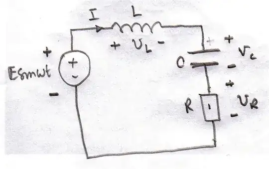
The Associated Variables Convention is used. You assign a current direction to each circuit element and then assign a plus sign at the point at which the current enters the circuit element. A negative sign is assigned to the other end of the element and this then defines the voltage across the element as shown in the diagram below.

enter image description here

You then apply Kirchhoff’s voltage law to the circuit by going round a complete loop and assigning the sign you first come to on entering the circuit element to the voltage.
So starting at the bottom left-hand corner of the circuit in the diagram above and going around the circuit in a clockwise direction you get

$- E \sin(\omega t) + v_L + v_C +v_R = 0$

$\Rightarrow - E \sin(\omega t) + L \frac{dL}{dt} + \frac q C +I R = 0$

There is a detailed explanation of this convention in the “MITx: 6.002.1x Circuits and Electronics 1: Basic Circuit Analysis” course which is running at the moment. There is also an excellent free textbook available when you register for this course.

The method described above works and predicts voltages and currents in circuits correctly.

From the point of view of the Physics there is however a fatal flaw.
It is that you cannot apply Kirchhoff’s voltage law when there is a changing magnetic flux through a circuit.

The correct equation to apply is

$- E \sin(\omega t) +0 +\frac q C +I R = - L \frac{dL}{dt} $

There is a detailed explanation of this in Professor Lewin’s lecture on electromagnetism (16) and also it is worth looking at a couple of his subsequent lectures.
There are some notes here.

You will note that both methods produce the same final equation but only one of them is produced with the application of correct Physics.

Farcher
  • 104,498