I'd like to expand my earlier comment into a little essay on the severe practical difficulties in performing the suggested experiment.
I'm going to start my asserting that we don't care if the experiment is a "two-slit" per se. It is sufficient that it is a diffractive scattering experiment of some kind.
However, we do care about having
spacial resolution good enough to distinguish which scattering site (or slit) was the one on the path of the alleged particle
the ability to run the experiment at low rate so that we can exclude multi-projectile or beam/beam interaction as the source of any interference that we observe. (Though it's going to turn out that we never even get far enough for this to matter...)
Now let's get down to designing the beast.
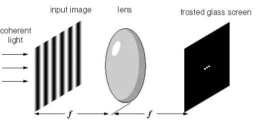
To start with we should note to any casual readers that the diagrams you see in pop-sci treatment are not even remotely to scale: typical classroom demonstration kit for use with lasers has the slits set less than $1\,\mathrm{mm}$ apart and uses projection distances of several meters or more to get fringes that are separated by a few centimeters. Or then use much closer set slits to get large angles.
The angular separation between maxima is on order of
$$ \Delta \theta = \frac{\lambda}{d} \,,$$
where $\lambda$ is the relevant wavelength and $d$ is the scattering site (or slit) separation. Allowing that the distance from the scattering surface to the projection surface is $\ell$, the spacial separation is (in the small angle approximation)
$$ \Delta x = l \Delta \theta = \frac{\ell}{d} \lambda \,.$$
Anna has suggested doing the experiment with electrons, which means that we're interested in the de Broglie wavelength usually given by $\lambda = \hbar/p$, and measuring their position en route with a tracking detector of some kind.
The tracking detector's spacial resolution is going to be the big barrier here.
Let's start by considering a Liquid Argon TPC because it is a hot technology just now. Spacial resolution down to about $1 \,\mathrm{mm}$ should be achievable without any breakthrough in technology (typical devices have $3$-$5\,\mathrm{mm}$ resolution). That sets our value for $d$.
Now, to observe a interferences pattern, we need a detector resolution at least four times finer than the spacial resolution.
Assume for the sake of argument that I use a detector with a $20 \,\mathrm{\mu{}m}$ spacial resolution. Maybe a MCP or a silicon tracker. That sets $\Delta x = 4(20 \,\mathrm{\mu{}m})$.
I also assume that I need $\ell$ to be at least $2d$ to be able to track the particle between the scattering and projection planes. Probably an under-estimate, so be it. Now I can compute the properties of the necessary electron source
$$\begin{align*}
p &= \frac{\hbar}{\lambda} \\
&= \frac{\hbar\ell}{d \, \Delta x} \tag{1}\\
&= 2\frac{\hbar}{\Delta x}\\
&= \frac{7 \times 10^{-22} \,\mathrm{MeV \, s}}{40 \times 10^{-6} \,\mathrm{m}}\\
&= \frac{7 \times 10^{-22} \,\mathrm{MeV}}{7 \times 10^{-12} c} \\
&= 10^{-10} \,\mathrm{MeV/c}\\
&= 10^{-4} \,\mathrm{eV/c} \,,
\end{align*}$$
which is safely non-relativistic, so we have a beam energy of $5 \times 10^{-9}\,\mathrm{eV^2}/(m_e c^2)$, and the tracking medium will completely mess up the experiment.
By choosing a $20\,\mathrm{m}$ flight path between scattering and detection and
getting down to, say, the $10\,\mathrm{\mu{}m}$ scale for $d$ we can get beam momenta up to $10^3\,\mathrm{eV}$ which at lest gives us beam energies about $1\,\mathrm{eV}$. But how are you going to track a $1\,\mathrm{eV}$ electron without scattering it?
I'm sure you can get better spacial resolution in silicon, but I don't think you can get the beam energy up high enough to pass a great enough distance through the tracking medium to actually make the measurement.
The fundamental problem here is the tension between the desire to track the electron on it's route which forces you to use nearly human scales for parts of the detector and the presence of that pesky $\hbar$ in the numerator of equation (1) which is driving the necessary beam momentum down.
The usual method of getting diffractive effects is just to make $d$ small and $\ell$ large enough to compensate for the $\hbar$ but our desire to track the particles works against us there by putting a floor on our attemtps to shrink $d$ and by because longer flight paths mean more sensitivity to scattering by the tracking medium.
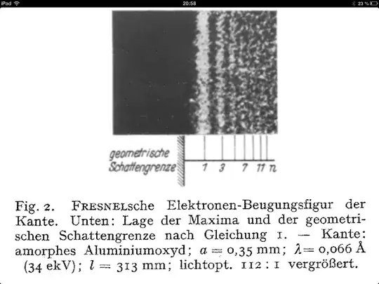 Source: Die Naturwissenschaften, Heft 44/45 1940
Urheber H. Boersch
Source: Die Naturwissenschaften, Heft 44/45 1940
Urheber H. Boersch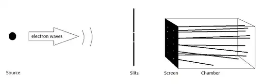