6

A recent question asked how to find the impedance of an infinite chain of series-plus-parallel circuits. The standard trick is to split the chain after the first link, and treat the tail of the circuit as a copy of the original, bigger circuit. That is, the circuit contains a copy of itself, which is fine as it is infinitely long.

enter image description here

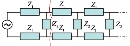
The corresponding equation for the circuit's impedance $Z$ is then

$$ Z=2Z_1+\frac{1}{\frac{1}{Z_2}+\frac{1}{Z}}, $$ which gives an easy quadratic equation in $Z$ with solutions $$ Z=Z_1\left[1\pm\sqrt{1+2Z_2/Z_1}\right]. $$

Now, for purely resistive $Z_1$ and $Z_2$ it is clear enough which sign the square root should have, since then $\sqrt{1+2Z_2/Z_1}>1$ and the minus sign is ruled out by the condition that $\mathrm{Re}(Z)\geq 0$ (unless one is OK with free energy coming out of nowhere).

However, this need not be the case. An easy example is where $Z_1=1/i\omega C$ is capacitive and $Z_2=i\omega L$ is inductive, in which case $$ 1+2Z_2/Z_1=1-2\omega^2 LC $$ can, depending on $\omega$, be smaller than one, giving two distinct possible values for $Z$. This result will hold if both impedances have small but nonzero resistive components, which is a more physical situation. An infinite chain of coupled oscillators has all the makings of a wave line, but that does not mean that the impedance of the line can suddenly have two different values.

How does one resolve this? What are the conditions on $Z_1$ and $Z_2$ for this to be a problem? How does this relate to the continuum limit on the transmission line?

Emilio Pisanty
  • 137,480

1 Answers1

-1

OK. Let us start with the initial equation

$$Z=Z_1\left[1\pm\sqrt{1+2Z_2/Z_1}\right] \tag 1$$
and consider lossless circuit. It is a good idea to determine the value of $Z_1$ as $Z_1=ix_1$ and similarly, $Z_2=ix_2$ where $x$ denotes the reactance.

For the the capacitive reactance $x<0$ and for the inductive reactance $x>0$. We have:

$$Z=ix_1\pm\sqrt{-(x_1^2+2x_1x_2)} \tag 2 $$

Now, we see that the following condition must apply:
$$x_1^2+2x_1x_2>0 \tag 3$$ In the opposite case the impedance $Z$ will contain a real part, and hence the circuit will consume or give energy, depending on the sign of the real part.

The question boils down to the choice of the sign of square root.

For this we assume that the impedance $Z$ contains a small ohmic resistance $r_1$. That means we take $Z_1=r_1+ix_1$ in $(1)$.

The next step is to expand $Z$ into Taylor series with respect to $r_1$. I jump over the math part and write only result

$$Z=r_1+ix_1+ \sqrt{x_1^2+2x_1x_2}\left ( i+\frac{r_1}{x_1}\right ) \tag4 $$

The sign of the square root in $(4)$ should be selected so that the real part of this expression was positive.

Let $x_1>0$. Because $r_1>0$, then in order that the real part of $(4)$ would be positive we must take the sign $+$ in front of the square root.

Let $x_1<0$. Because $r_1>0$, then in order that the real part of $(4)$ would be positive we must take the sign $-$ in front of the square root.

Finally, looking at the process $r_1\rightarrow 0$, we come to the end result:

$$ Z=\left\{ \begin{matrix} ix_1+i\sqrt{(x_1^2+2x_1x_2)} \;\text{ if}\; x_1>0, \\ ix_1-i\sqrt{(x_1^2+2x_1x_2)} \;\text{ if}\; x_1<0. \end{matrix}\right. $$ Remember that $(3)$ must hold.

But what happens when $(3)$ does not apply?

It is impossible in this case to develop a stationary sinusoidal regime in the circuit and the concept of impedance is meaningless.

Emilio Pisanty
  • 137,480
Martin Gales
  • 2,727