3

I have a Raspberry Pi and it requires a Externally Powered USB hub to run Portable HDD on it. So what if I connect +5 and GND port of the USB Client to external power source of 5V-1A directly rather then connecting them to the USB Host ? OR What if I use a transistor as a switch and for source isolation ? Will this work or not ? Or Do I have to give power to D+ and D- ports too ?

schematic

simulate this circuit – Schematic created using CircuitLab

Parth Parikh
  • 419
  • 4
  • 14

1 Answers1

3

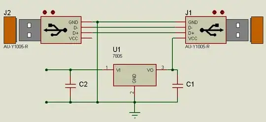
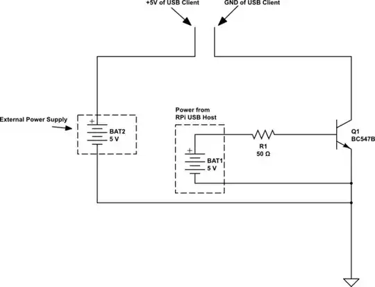
Connect the data lines from the USB port to the device, connect the ground of the external power supply to the USB ground and connect the external supply positive line to the device side USB supply only

Here is one example that shown the described connection scheme using a linear regulator as power source (limited to 1A that may not be enough) but you can use any 5v source.

enter image description here


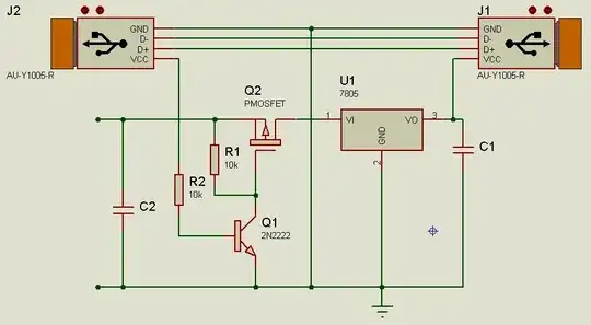
In order to switch the power of the USB client when the plug is removed you can use a mosfet that turns on when the plug is inserted to the PC.

When there is no Vcc voltage in the base of the transistor the resistor R1 works as a pullup and keeps the mosfet off by keeping the gate high.
When the plug is inserted the PC side Vcc is applied to the base of the transistor so the current that flows through it creates a voltage drop across R1 and turns on the mosfet.

Note that the mosfet should be a logic level type that turns fully on with -5v Vgs.
Also the input should not exceed the max allowable Vgs (usually 20v but this is absolute max)

enter image description here


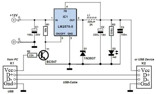
Another alternative is when a switching regulator is used that has a control pin, in that case the PC side Vcc supply can be used as a signal to turn the regulator on when the USB plug is connected.
The following schematic (I've modified the USB plugs slightly) shows such an example using a 1A switching regulator but the same principle applies to switching regulators of higher current.

enter image description here

alexan_e
  • 11,130
  • 1
  • 29
  • 62
  • Can you explain how does this work ? I didn't get why connecting D+ but not Vcc and GND to external power ? – Parth Parikh Dec 29 '13 at 11:19
  • @ParthParikh D+ and D- are the data lines, they transfer all the data between the device and PC. On the other hand the Vcc of the PC USB plug is just a power source so instead of getting the power from the PC you connect your own power supply. The ground connection is needed so that all devices have a common reference point (the PC, the device and the external power supply). – alexan_e Dec 29 '13 at 11:23
  • @ParthParikh I just noticed that the schematic is messed up, give me a minute to correct it. – alexan_e Dec 29 '13 at 11:25
  • This might be on the web, but it is nonsense. The pin names are non-standard, but assuming - and + mean the D- and D+ data pins, it makes no sense to supply power to D+! My best guess is that the author confuses the + and VCC pins. (And note that 1A with 7V drop means 7W: get a sizeable heatsink for the 7805!!) – Wouter van Ooijen Dec 29 '13 at 11:27
  • @WoutervanOoijen You are absolutely right, I was just searching for a relevant schematic that showed what I was describing and didn't notice that the shown connections were wrong. I have removed the linked article and updated with a schematic I made using a linear regulator as an example but surely an external supply using a switching regulator would be more efficient. – alexan_e Dec 29 '13 at 11:36
  • @alexan_e This means I can directly plug external power between GND and Vcc without messing with D+ and D-. Now I just need to get regulated 5V-12W power for HDD. That would be better with switching regulator. – Parth Parikh Dec 29 '13 at 11:41
  • @ParthParikh Yes, the connection of D+ and D- stays as it. You just need to cut the connection of the Vcc pin coming from the PC side or you'll get a short between the two supplies . – alexan_e Dec 29 '13 at 11:46
  • What about the transistor that switching circuit ? It will be automated switch to power the client. (However I need to modify it to bear 12W) – Parth Parikh Dec 29 '13 at 11:52
  • @ParthParikh I have updated the reply – alexan_e Dec 29 '13 at 12:07
  • @alexan_e: if you power the RPi from the same 5V power supply as the USB disk, then you don't have to worry about shorting the 5V pins. A 7805 will definitely not be enough for that case, though, as the RPi + a HDD will need a lot more than 1A. – Laszlo Valko Dec 29 '13 at 13:42
  • @LaszloValko The short I described was in case that two outputs are connected together such as the PC side Vcc and the output of an external supply.v If we are talking for the client side then several power inputs can be wired in parallel assuming that the current of the supply is enough to supply them all. – alexan_e Dec 29 '13 at 14:19
  • @alexan_e: well, the OP was asking about RPi, and not a PC as the host. RPi needs a 5V power supply, and supplies the same 5V to its USB host ports. In this respect, when you connect the 5V input of the RPi to some power supply, connecting the USB Vcc outputs of RPi to the same power supply will not cause a short. – Laszlo Valko Dec 29 '13 at 14:25
  • @LaszloValko Yes you are correct on that, I originally misunderstood the configuration you described. – alexan_e Dec 29 '13 at 14:32
  • @LaszloValko - I posted this question to clarify what I think you're describing since it's a different case than the solution that was accepted. – TomG Jan 27 '14 at 02:25