I am considering cascading two triacs like this in order to make a solid state relay. I'm not going to control the phase angle of the voltage on load as done in dimmers. I only want to make an electronic switch which turns on or off a resistive load for long time durations (minutes to hours).
I have some doubts on the output waveform of this circuit.
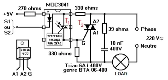
We assume that the LED in MOC3041 is always lit. At the zero-crossing points of the 220V AC sinusoidal voltage, both T1 and T2 will be turned off. When a positive or negative half cycle starts, T1 will conduct first and start supplying gate current to T2. T2 will stat conducting as soon as it has enough gate current. This waiting time brings out an issue of time delay which will clip the voltage waveform on the load.
How do I calculate this time delay? I'm aiming to find out whether this delay time will cause great distortion on the waveform, or it is negligible. Can this circuit be used for switching AC voltage under the given conditions?
(Assume that the frequency of the AC voltage is 50Hz.)