Some ideas for you to consider:
1. Use the correct opto-isolator.
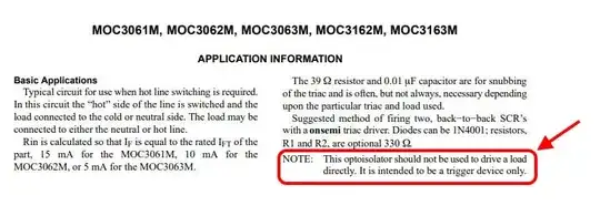
The MOC3063 is not intended to drive a load directly, it is designed to trigger a TRIAC, which is not the same function as driving a relay coil, refer last page of the datasheet, screenshot below:
2. Snubber design.
To design a snubber in a switching application (such as this), you need to have the following data:
A good electrical model of the load that is being switched.
A good understanding of what the snubber is intended to do, for example:
(a) Protect the load from harsh di/dt and/or dv/dt, and from over-voltage & over-current.
(b) Protect the switching device from harsh di/dt and/or dv/dt, and from over-voltage & over-current.
(c) Mitigate EMI (electromagnetic interference).
(d) A combination of the above.
A set of requirements of what the voltage and current waveforms should look like (for both the load, and the switching device) during (a) turn-on and (b) turn-off.
I can help with item (1). However, for items (2) & (3) I would need extra data about your application, and it is greatly dependent on the switching device being used (which we know from point 1 of my answer that the MMOC3063 is not the best choice here). Also, it can become a complex process if you want to do it properly, so let's ignore this for now.
Update 2023-12-04:
After the data is available, and it comes time to design an RC snubber to suit an inductive load, this will be a useful starting point:-
How to design an RC snubber for a solenoid relay driving an inductive load??
2.1. Determining a model for the load.
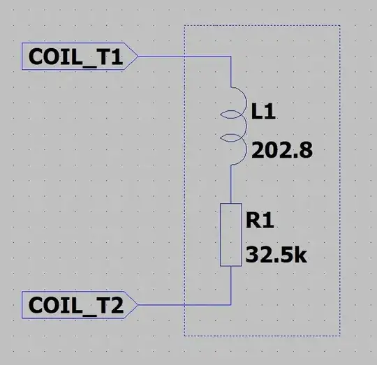
In this case, the relay coil is the load, and you need to work out its equivalent circuit. Let's assume it can modeled as a series connection of an R and an L. The value for R is provided by the datasheet, but the value for L is not provided directly, but it can be computed by using the coil data, refer screenshot below:

Assuming you are using the coil rated for 230VAC, we see that "Coil resistance" is 32.5kΩ, and "Rated coil power VA" is 0.74VA. Now, just to check we are on the right path here, we can ask the question: "If the coil had no inductance, what would be the VA rating we would expect?" Let's calculate the VA rating at the rated voltage (230VAC 50/60Hz) due purely to the resistance, which we can calculate from the current that would flow in the coil:
Icoil = 230VAC / 32.5kΩ = 7.08mA.
VAcoil = 230VAC x 7.08mA = 1.63VA (in this case, the VA can be replaced with watts, since the load is purely resistive).
We see that 1.63VA is much larger than the stated VA rating of 0.74VA. That means that this coil has significant inductance, which would impact any snubber design.
Some simple complex number arithmetic allows us to compute the impedance of L, from which we can then compute L, assuming AC frequency (50Hz):
Icoil = 0.74VA / 230V = 3.22mA.
|Zcoil| = 230V / 3.22mA = 71.5kΩ.
Where "|..|" notation indicates the magnitude of a complex number.
Now, let's use "XL" as the impedance of the coil inductance, and "^2" to mean "squared", we can write:
|Zcoil|^2 = R^2 + |XL|^2 (from Pythagoras.)
|XL|^2 = |Zcoil|^2 - R^2.
Plugging in the values, we find that:
|XL|^2 = (71.5kΩ)^2 - (32.5kΩ)^2
= 4.056E+09
|XL| = 63.7kΩ. Which is much larger than the coil resistance!
Using XL= 2πF.L, we re-arrange to get:
L = XL / (2πF)
Assuming F = 50Hz, we get:
L = 63.7kΩ / (2π50)
= 202.8H.
Yes, that is over 200 Henries, which is a huge value of inductance. Here is the equivalent circuit of your relay coil, note that the connection between R1 & L1 is simply not accessible to the outside world:
Out of interest, the time constant of the series L & R is:
Tau = L / R
= 202.8H / 32.5kΩ
= 6.24ms.
...which is comparable to the period of the excitation (a 50Hz sinewave has a half-period of 10ms), so yes, the inductance will indeed have a significant effect for the use-case of this load, so it must be taken into consideration in the design process - it cannot be ignored.


