2

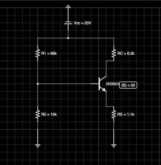
The question gives the following schematic and says to find the Q point for the Voltage(Collector to Emitter) and the Q point for the Collector Current. It gives beta as 50.

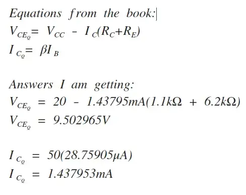
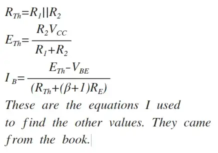
I'm using two standard equations from my book to find the (Q) point for the Voltage(Collector to Emitter) and the Collector Current. I followed step by step instructions from the book and I'm being told I'm wrong. Could someone calculate these two values and maybe tell me where I went wrong.

I'm told that when finding the (Q) point I can't use these two equations because (B) beta is completely independent. But when I look in my book all the equations are identical to the ones finding a value related to a (Q) point. I've listed the equations below with my answers.

Equations Equations Circuit

Shane Yost
  • 1,059
  • 7
  • 16
  • 31
  • What are you assuming for Vbe? How did you determine the value of Ib? – Joe Hass Aug 06 '13 at 01:26
  • .7 for base to emitter voltage – Shane Yost Aug 06 '13 at 01:27
  • I thevinized the circuit by calculating R(th) first which is defined as R1||R2. Then i found the thevinin voltage (Eth) which is considered Vb also and is found by taking (R2*Vcc)/(R1+R2). After this i used the following equation to find Ib. (Eth - Vce)/(Rth + (B + 1)Re) – Shane Yost Aug 06 '13 at 01:30
  • I posted them above if that helps. All equations came from my book FYI. However, I'm told they are wrong for calculating the Q point but I see no reason nor evidence in why that is. I just want this to be over with cause it's giving me a headache. Your help is appreciated whether it supports I'm wrong or not. – Shane Yost Aug 06 '13 at 01:37
  • The resistor values as you put them into the schematic are the values for which you are asked to calculate the Q point, right? They are not a result of some calculation? – user36129 Aug 06 '13 at 09:28
  • I suggest you try a different approach. You are using linear circuit analysis techniques for a non-linear circuit. What happens if you assume that the transistor beta is infinite, so that Ib is zero but Vbe is still 0.7V? The solution for a beta of 50 must be pretty close to that. – Joe Hass Aug 06 '13 at 11:10
  • Yes the resistor values are given along with Beta and Vbe being .7V – Shane Yost Aug 06 '13 at 15:37

1 Answers1

0

The most important thing to recognize in this circuit, is that the current through R1 and R2 is not equal and that everything can be solved algebraically. Let's just write down everything we know and see where we land. In this notation, \$I_x\$ means the current through x

  1. \$(I_{R_2}+I_B)R_1 + I_{R_2}R_2 = 20 V\$
  2. \$(I_B+I_C)R_E + V_{CE} + I_CR_C = 20 V\$
  3. \$I_C = \beta * I_B\$
  4. \$(I_B + I_C)Re + V_{BE} + (I_{R_2} + I_B)R1 = 20 V\$

This system of equations has too many unknowns: \$I_{R_2}, I_B, I_C, V_{BE}\$ and \$V_{CE}\$. We need to either find a fourth independent equation or guess one of them. I assume that you are being expected to assume that \$V_{BE}\$ is constant, as per your statement that it is 0.7V. This allows you to solve this system of equations:

  • \$I_B = (20 - 0.7 - {R_1* 0.7\over R_2})/(R_1 + R_E*(1+\beta) + {Re*R_1*(1 + \beta)\over R_2}) = 28.75904 µA\$
  • \$I_C = 50*I_B = 1.43795245 mA\$
  • \$I_E = I_B + I_E = 1.46671149 mA\$
  • \$V_{CE} = 20 - I_ER_E - I_CR_C = 20 - 1.613382639 - 8.91530519 = 9.471312171 V \$
user36129
  • 8,328
  • 31
  • 38