3

This question was initially asked at StackOverflow as a Verilog question, but, eventually, it became more hardware than software discussion.

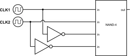
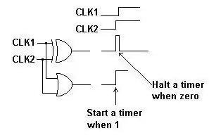
The question: how simultaneous (positive) edges of two asynchronous clocks might be detected in digital circuit.

The original question did not contain any information about how much time "simultaneous" is, therefore your suggestions and thoughts on this are also welcome. For clarity, let's define "simultaneous" as 0.5 or 0.25 times the period of the slower clock.

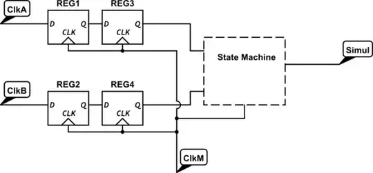
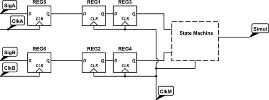
One of the proposed solution uses non-standard flip-flop configurations described in the following patents: US6320442 B1, US5793236 A, US5327019 A. Is this approach 100% safe, or there is still chance of overlooking the event in question (due to internal metastability, or any other reason)?

Is there a standard approach in dealing with this kind of tasks?

EDIT:

There were few solutions suggested, but none showed explicitly how exactly the information about the occurrence of simultaneous edges may be (reliably) fed into digital logic. Please note that (essentially) this is the question, and any solution which do not address this subject is incomplete.

Vasiliy
  • 7,443
  • 2
  • 21
  • 38

3 Answers3

2

The simplest pure-hardware way would be the circuit below.

schematic

simulate this circuit – Schematic created using CircuitLab

This works because there's a propagation delay through the inverters. During that propagation delay, the bottom two inputs will still be high, pulsing the output of the NAND gate. You just have to make the propagation delay long enough to satisfy the setup and hold times of the NAND, but short enough that it will completely discharge between clock cycles.

It's timing sensitive but definitely doable. People do it by accident all the time.

Karl Bielefeldt
  • 1,734
  • 11
  • 20
  • 1
    One nice thing about this circuit is that provided the length of every input pulse exceeds the propagation delay of an inverter, the circuit will always be well-behaved. Depending upon how close the inputs switch, the output may be a runt pulse (which may cause metastability in downstream circuits) but this circuit will behave cleanly. – supercat Jun 22 '13 at 00:11
  • 1
    I wouldn't say that this circuit behaves cleanly if it gives runt pulses to the downstream logic. Proper behavior is also so very dependent on the timing of the inverters that it is unlikely to work consistently over process/temp/voltage variations. The general operating theory of the circuit is nice, but implementing it properly and reliably would be problematic. –  Jun 22 '13 at 02:20
  • I agree with @David Kessner. I think that any proposed solution, which does not explicitly show how exactly the detector interfaces to clocked domain of digital circuit, is incomplete. I'm sure that there are hundred schemes which may perform the detection of the required conditions, but as long as you can't capture this detection reliably - there is no value in this solution. Adding clarification to question. – Vasiliy Jun 22 '13 at 06:41
1

I've edited my answer to show the circuit diagram with more detail and also cover the questions in the comments from David Kessner and Vasiliy Zukanov: -

enter image description here

Two gates are used; the OR gate has to be zero before a timer clocked with what I've called "super-clock" is primed. Once it is primed it then starts counting as soon as either CLK1, CLK2 or both go high.

It finishes timing as soon as a zero is detected on the output of the EXOR gate.

2nd EDIT to provide information that is a little clearer.

Super-clock is a clock running significantly higher than CLK1 or CLK2. The period of super-clock is many times smaller than the period of either CLK1 or CLK2.

If the timer doesn't count to anything after being primed and triggered it is because the positive edge time difference between CLK1 and CLK2 is insignificant.

If it counts to 1 and no more then it can be assumed that the time delay between CLK1 and CLK2 is between zero and one-super-clock period i.e. it is still insignificant. If it counts to two or higher than this can be arbitrarily taken as the two clocks not rising synchronously.

Andy aka
  • 456,226
  • 28
  • 367
  • 807
  • This doesn't work if the two clocks are different frequencies or different duty cycles. –  Jun 21 '13 at 19:53
  • When you say "timer" you're probably referring to some circuit containing flops. With what clock are these flops clocked? Use either one of two clocks in question, you're still getting metastability issue in timer. Doesn't seem like a good solution. – Vasiliy Jun 21 '13 at 20:06
  • @DavidKessner the condition for starting the timer have to be met and that is both clocks have to be at zero to prime the circuit. Shouldn't that mean that the circuit doesn't care that they may be of different frequencies? I may be wrong about that of course but i was just trying to measure the point at which both clocks were at zero to prime the timer circuit. – Andy aka Jun 21 '13 at 20:13
  • @Vasiliy The timer I referred to is ill-defined but I didn't assume it would be clocked from one of the two clocks but rather from some arbitrarily high super-clock that was able to "measure" the time difference. If this isn't allowed then please modify the question. – Andy aka Jun 21 '13 at 20:16
  • Your "super-clock" can't be synchronous to both input clocks because they are asynchronous, therefore, no matter what do you mean by "super-clock", the metastability issue remains. Maybe I'm missing some major point in your idea? Can you add schematic of the complete circuit? BTW, your timer will be enabled also when one of the clocks goes low while the other is still high. – Vasiliy Jun 21 '13 at 20:35
  • @Andyaka What you describe is actually closer to this kind of phase-frequency detector commonly used in PLL's. Here'a a link to a diagram: http://2.imimg.com/data2/JR/GW/MY-719802/a-250x250.jpg –  Jun 21 '13 at 20:40
  • @DavidKessner yeah I was basing it on the ADF4111 frequency phase detector http://www.analog.com/static/imported-files/data_sheets/ADF4110_4111_4112_4113.pdf – Andy aka Jun 21 '13 at 21:28
  • @Vasiliy I'm assuming the super-clock time period is significantly higher than either clk1 or 2 and that if it doesn't count anything when the pre-conditions are met, this is the measure of the two clocks rising simultaneously (within one time measure of the super-clock). – Andy aka Jun 21 '13 at 21:31
  • @Vasiliy the timer starts when the OR gate goes high i.e. both clocks are low and one (or the other, or both) rises high. I'm no digital expert so maybe I'm missing something. I'll try a better circuit diagram. – Andy aka Jun 21 '13 at 21:33
  • @ Andy aka, you meant to say that the time period is much shorter, right? I still can't grasp the whole picture of the solution you propose. I'm familiar (basically) with the theory of PLLs, but I can't see how the output of PLL's phase detector may be directly fed into digital logic without causing metastability issues. I'm sure that if you'll put a complete schematic diagram of the solution it will be much easier to discuss it. – Vasiliy Jun 22 '13 at 06:34
  • @ Andy aka, furthermore, I believe that the outputs of the gates you've shown need to be synchronized to "super-clock" clock domain. Otherwise, what assumptions about possible metastable states of the timer have you made? – Vasiliy Jun 22 '13 at 06:55
  • @VasiliyZukanov I'm not sure what I need to do. The way I see it working is that if the "super" count is zero when the ex-or is zero then the two clocks had rising edges that occured simultaneously (within one super-clock time period). I'm not a digital expert and I don't understand about possible metastable states of the timer I may have assumed. – Andy aka Jun 22 '13 at 10:29
1

I don't think this should be difficult. Assuming you have master clock that is faster than either of Async clocks, all you need is 2 sets of double synchronizers and a state machine running in master clock domain to "detect" events. This setup will give resolution of 2 cycles in master clock domain for definition of "simultaneous". So that will dictate what minimum frequency master clock should be.

schematic

simulate this circuit – Schematic created using CircuitLab

It is absolutely important that ClkA and Clkb are true clock signals without transients. If these were termed as simple signals, I would add a flip flop in front of synchronizer in that clock domain as such.

schematic

simulate this circuit

State machine should be straight forward where any transitions from 00 to 11 or 00->01/10->11 happening in 1 or 2 cycles.

mj6174
  • 664
  • 1
  • 5
  • 11
  • Seems correct. This answer is a variation on the Alex Rellim's answer in the original question (except that that answer lacked proper synchronization, proper timing definitions and its state machine was too simple). Combined with the solution by @Andy aka (for state machine) this gives a programmable functional detector of simultaneous occurrence of clock edges, where "simultaneous" is defined in terms of periods of the capturing clock. The constraint is that capturing clock must be > x2 faster than any of the source clocks. Can someone prove that x2 is the lowest limit? – Vasiliy Jun 23 '13 at 19:58
  • I must accept this answer, but I'm not completely satisfied with it. This solution is kind of "brute" force ("brute" refers to oversampling). I don't believe that this is the best that can be achieved. – Vasiliy Jun 23 '13 at 20:03