I made a triple PWM motor controller with a 555 timer hooked up to 3 IRF621 MOSFETS to the motors. I am having interference troubles. When I turn one knob up, the other motor wants to change speed a small amount, and it is not stable. I added a 47pf capacitor from pin 5 to ground on each, but that didn't seem to help. Is there a way around this, or is that just how the 555 timer is? Here is the schematic I made (yes I know it is a very bad schematic).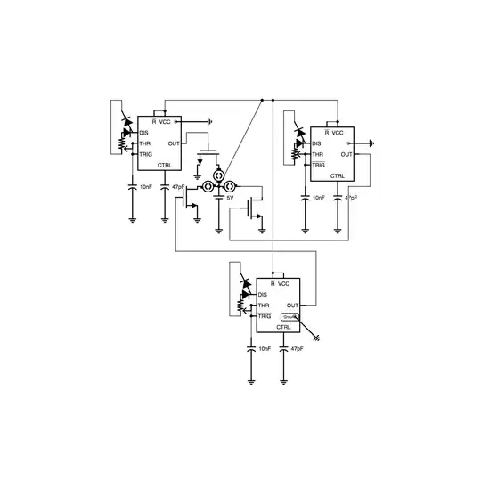
Asked
Active
Viewed 3,774 times
5
skyler
- 10,196
- 28
- 81
- 132
-
1Yeah, that's why people hate the 666 timer chip. It is from the devil! :) It is also unstable or unusable in many applications due to it's variability. Other than possibly people making super cheap toys, no professional EE that I know of uses 666 timer chips. – Jun 10 '13 at 22:32
-
I cant find the datasheet of the 666 anywhere :( they are probably too embarrassed to put data on it – skyler Jun 10 '13 at 23:40
-
I designed a clone of the LM666. Here are the design files, with pics: http://www.thingiverse.com/thing:92778 – Jun 11 '13 at 01:25
-
Oh cool, so that was you! I saw it earlier!! – skyler Jun 11 '13 at 01:27
-
Guilty as charged. – Jun 11 '13 at 01:32
-
I'm wondering how this circuit works at all. Doesn't there need to be a resistor between Vcc and the DIS pin, in order to charge the cap during the charge portion of the cycle? – jwygralak67 Jun 11 '13 at 17:44
-
Oh yeah, That was my bad, I forgot to draw the resistor in. Dumb me – skyler Jun 12 '13 at 02:21
1 Answers
5
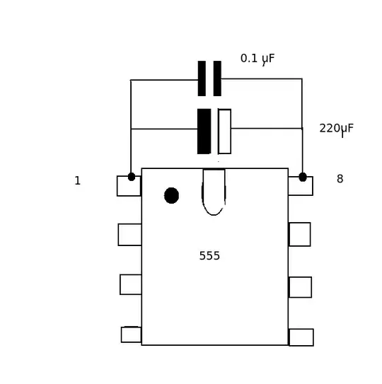
I notice from your circuit that the 555 and motors are running from a common (5V) power supply without any form of decoupling. The 555 is a current hog and draws a surge of current from the supply every time its output changes.
Try putting a large electrolytic (say 220uF) and a 0.1uf (helps with high frequencies) across each the Vcc and ground pin of the three 555s.
I would also make the capacitor at pin 5 a bit bigger (say 0.1uF) - its job is to smooth out any noise of the internal divider chain of 5K resistors. 47pF is way too low.
JIm Dearden
- 19,036
- 30
- 40