1

I am not sure if circuit reviews are allowed on this forum, but if not, just tell me.

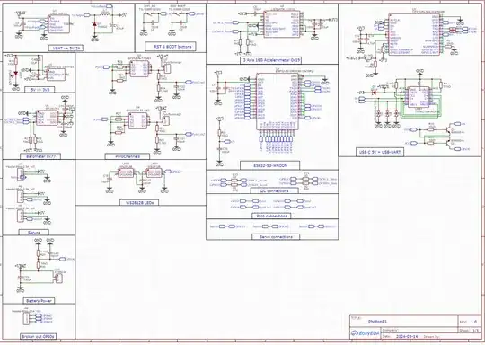
For the last few weeks I have been working on a model rocket flight controller which is supposed to calculate the altitude and acceleration with a barometer and accelerometer.

The MCU is an ESP32-S3-WROOM, which I have experience with. I also added the ability to fire pyro charges via two pyro channels, and to control three servos. All of this is powered with a 2S (7.4 - 8.4 V) Li-po battery, which can easily handle 25 A.

My biggest concerns are the USB-C interface, and the power management (voltage regulators, etc.), as these are the regions I have least experience with.

For now I only have a schematic, but I already started with routing all my parts. As I am still a newbie, and wouldn't like wasting money on many different PCB prototypes. I would be grateful if someone could look over this whole schematic (or certain sections they are experienced in), and point out any errors/mistakes I made. Feedback/suggestions about the "aesthetic" of my schematic is welcome. This is the schematic:

enter image description here

(I have just noticed, that I forgot to change the names of my servo pins, I will change that tomorrow)
ocrdu
  • 9,195
  • 22
  • 32
  • 42
Fazeli24
  • 97
  • 7
  • 2
    Please don;t split your schematic too much. Having one or two extra boxes on top of the main one is fine. But like this, it's hard to have a global view of the circuit. – Fredled Mar 27 '24 at 22:07
  • Do you real;y need these resistors when pins are connected to GND or 3V permanently? The only reason for this would be to protect the inputs from strong sudden surges or reverse current. But are these events likely? – Fredled Mar 27 '24 at 22:09
  • Okay, this is one of my first schematics, so this "style" of organizing everything seemed logical to me, my first schematic had connections going everywhere, often above other wires. This made it only hardly readable, and so this is what I ended up with. But that is just my opinion, i am happy about any suggestions. Regarding the Resistor, I am not quite sure which one you mean, could you maybe write their number? – Fazeli24 Mar 27 '24 at 22:22
  • 3
    If it can be at all avoided, do not use net names to connect nodes. It becomes impossible to read and therefore becomes meaningless. There is a particular skill to drawing schematics that is mainly lost here. – Andy aka Mar 27 '24 at 23:36
  • To reinforce the other comments about the style of the schematic. Think of it as a map, or as a picture. Software is happy with a list of net names and pins, humans need pictures. What you've presented is impossible for us to review accurately and easily (pick 1 out of 2). If you do want to reduce the clutter of many GPIOs going everywhere, then draw them as a bus, and rip out the I2C and servo connections etc at the appropriate places. – Neil_UK Mar 28 '24 at 06:14
  • Okay, thanks for all your feedback! I will redo the schematic with your suggestions. Although it would be very nice, if someone could send me some links to "good" schematics. My main inspiration was adafruit, the official esp32 dev module schematic (https://youtu.be/S_p0YV-JlfU?si=JQCdCQ5FEVL0QFAe) , and many YouTubers like Robert Fenarec(https://youtu.be/S_p0YV-JlfU?si=JQCdCQ5FEVL0QFAe). – Fazeli24 Mar 28 '24 at 08:54
  • I think you need some functional safety on your pyro channels. It would take much to falsely fire so consider adding an interlock relay and means of testing the pyro circuit resistance. – Kartman Mar 28 '24 at 09:00
  • @Kartman I have a continuity check there, and the MOSFET Gate is pulled low to ensure a closed MOSFET – Fazeli24 Mar 28 '24 at 09:13
  • What ensures that the esp32 won’t do something wrong? If everything works there is no problem, but if something fails you may get an unintended firing. You also have no ESD ,EMC or overcurrent protection. – Kartman Mar 28 '24 at 12:42
  • @Kartman Yeah, I only have ESD protection on my USB C Port, might as well add some to other parts of the circuit, like my broken out GPIO pins. I use the ESP32-S3-WROOM module, which comes with a metal shielding, so I thought that EMC wouldn't be a problem. Overcurrent protection on my 5 V Servo and 3.3 V rails seems plausible. An interlocking relay does sound interesting, but because all the ones I found are big and quite heavy, they aren't really suitable for model rocketry, where every gram counts. – Fazeli24 Mar 28 '24 at 13:27

0 Answers0