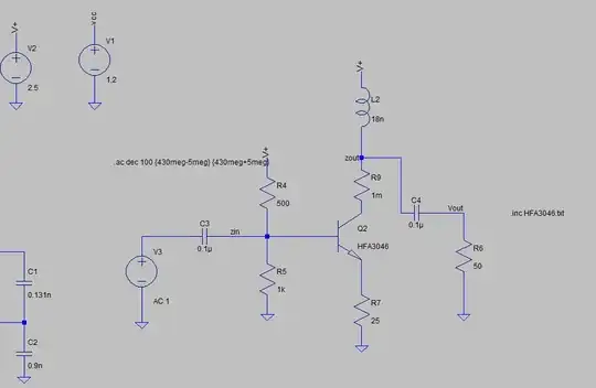
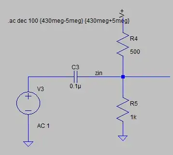
Test it with a resistor alone (e.g., disconnect Q2). Is it still negative? If so, you are now sure that it must be a resistive load, and there is no feedback or nonlinearity affecting the measurement.
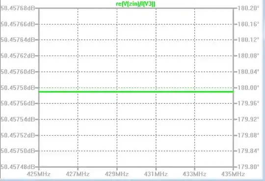
Simply negate I(V3), or multiply by -1.
The insight: current through a SPICE component is into the first or positive terminal. Thus, a DC source, delivering power, reads negative current. This remains true in AC analysis.
You may also want to check over wider bandwidths, from time to time. Your analysis range of 425-435MHz shows no curvature, but it could be an overly-zoomed section of a much broader arc between the upper and lower cutoffs of the amplifier. Checking to include these cutoffs, may reveal phase inversion or peaking that is suggestive of instability, wiring mistakes, or erroneous component values, and thus you can weed out more errors more quickly.


