0

The TI TLC6983 LED driver datasheet provides decoupling capacitor recommendations for the IC supply pin, in 10 : Power Supply Recommendations:

Decouple the VCC power supply voltage by placing a 0.1 μF ceramic capacitor close to VCC pin and GND plane.

The datasheet, however, provides no approximate decoupling capacitor recommendations for the LED supply pins:

Depending on panel size, several electrolytic capacitors must be placed on the board equally distributed to get well regulated LED supply voltage VR/VG/VB. The ripple of the LED supply voltage must be less than 5% of their nominal value.

• C.led

What is a practical approach to determine the approximate amount of capacitance to start with? I assumed 4 x 10 µF ceramic capacitors (I can't use the recommended electrolytic due to the leakage).

• C.cc and C.led

There is no mention, but is it generally recommended to also include a smaller package 100 pF or 10 pF ceramic capacitor even closer to the pins for noise filtering, as depicted below?

Decoupling capacitors

ocrdu
  • 9,195
  • 22
  • 32
  • 42
kando
  • 391
  • 1
  • 9

2 Answers2

2

What is a practical approach to determine the approximate amount of capacitance to start with? I assumed 4 x 10 µF ceramic capacitors (I can't use the recommended electrolytic due to the leakage).

You have to provide enough to keep the ripple below 5% on the LED supply voltage. How much will depend on how many pixels you're driving, how many controllers are in your array, how bright you're driving them and how far away the voltage regulator supplying the rails is. For example if you have a fast onboard SMPS that is regulating in real time, then you probably don't need a lot of bulk capacitance beyond what the switcher requires. If you're running a display that is at the end of a 10m cable from the power supply, you're probably going to need a lot of it to suppress ripple.

MLCCs will make this harder than electrolytics, but if you want to do that, digikey is quoting ~ 5 cents for an 0603 with 10uF effective capacitance at 3V bias (22uF nominal). I'd put 5 or 10 per controller on your prototype and measure the ripple under your specified operating conditions as you add more. In production remove or just don't populate the excess pads.

There is no mention, but is it generally recommended to also include a smaller package 100 pF or 10 pF ceramic capacitor even closer to the pins for noise filtering, as depicted below?

This is an LED power supply and they're recommending electrolytics, so very high frequency decoupling is not important.

If it were important, for high frequency noise filtering you want to use the smallest possible package with the lowest inductance loop, but there isn't a lot of point in using a 100pF capacitor when you could get a 100nF capacitor of the same size and similar inductance. You also want to be careful when mixing MLCCs of different sizes as they can have antiresonances. See: Antiresonance of multiple parallel decoupling capacitors: use same value or multiple values?

user1850479
  • 16,883
  • 1
  • 21
  • 46
2

First you need to know what the ripple current is.

The chip multiplexes the display: it turns on the rows of LEDs one at a time. So maximum ripple current would occur with a full dark row (zero current) followed by a full bright white row (48 x 20mA = 960mA).

If you're using separate supplies for RGB, that's 320mA per color. So for each supply, it can draw up to 320mA for a full bright row, then 0mA for a full dark row, then repeat.

If you're not using 20mA LED current then you can scale accordingly.

Frequency is not easily extracted from the datasheet, it is also configurable, but for a good visual aspect without flicker it should be pretty high. They mention about 3kHz max refresh rate, so with 16 rows each will stay lit for 20µs, which gives a ripple frequency from 24kHz (pattern of alternating bright and dark rows) down to a few kHz (top half rows bright, bottom half rows dark).

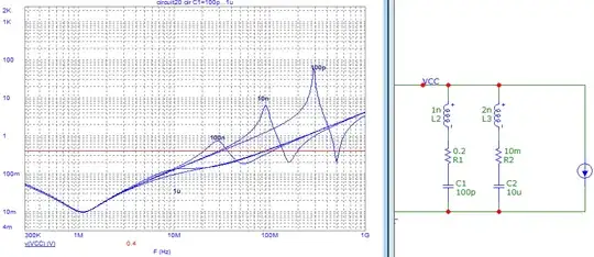
They require 5% voltage ripple on the supply, which means it should have an impedance below 3V * 5% / 320mA = 0.4 ohms in this frequency range. Say up to 50-100kHz for extra safety margin.

So you need to design your power supply to meet this required impedance. You'll probably be using buck converter(s) for the three supplies, and these have pretty low impedance at low frequency thanks to feedback. But at higher frequency this is no longer the case and the output caps are relied upon to provide low impedance.

10µF provides 0.4 ohms impedance above 50kHz. Below that it would rely on the buck converter's output impedance. So one will probably not get away with just one cap.

It's impossible to answer without knowing the output impedance of your buck converter, but... you get the idea: you should use enough capacitance to keep power supply impedance below what is required to get 5% ripple (at your LED current) in the desired range of frequency. Since you'll probably use several 10µF MLCC, high frequency should not be a problem. Low frequency (few kHz) should be taken care of by the buck converter, but you have to be careful not to have an impedance peak between the two. This is why they recommend electrolytic caps.

If you want less caps, then you need a buck that runs at high frequency, with a control scheme that ensures quick transient response, which is the time domain equivalent of "low output impedance up to higher frequency".

I can't use the recommended electrolytic due to the leakage

I have no idea what you mean by this, modern electrolytics have extremely low leakage current. However the board will probably get quite hot due to all these LEDs, so it would be a good idea to use 105°C low-ESR caps. I think 100-300µF should work well, but again it all depends on the characteristics of your buck converter.

If you use several 16x16 LED blocks powered from one supply you should also consider the maximum output capacitance the buck converter will tolerate, and/or perhaps tune the soft-start to make sure it does not freak out and go into short circuit protection mode due to the huge inrush current.

There is no mention, but is it generally recommended to also include a smaller package 100 pF or 10 pF ceramic capacitor even closer to the pins for noise filtering, as depicted below?

Bad idea. High frequency characteristics of MLCC are determined by inductance which means physical size (ie footprint). Capacitance only matters at lower frequency when inductance does not dominate total impedance. This means, if we compare two caps of the same footprint, the one with more actual µF (once biased) always wins. Using low capacitance caps is only interesting if you do a PC motherboard or big FPGA and you need 300 caps so shaving a fraction of a cent off each cap matters, which is not the case here. Or for RF where you may need a carefully tuned decoupling cap, thus an accurate value, thus C0G not X7R, thus low capacitance.

In fact pushing the larger caps away from the chip to insert the smaller caps in between may make it worse: unless you use a multilayer board with a ground plane right below top layer, most of the inductance is in the vias anyway, and the difference in inductance between a tiny cap and a larger one is not spectacular. Besides, mixing different values of caps will cause antiresonance peaks if you're not careful.

enter image description here

So I would recommend using one value of caps and getting a quantity discount on it. The value should be a balance between cost and the most µF that will fit in 0603 or 0805 in X75/X5R. For example, double the number of 10µF caps can be cheaper than 22µF caps due to quantity discount, and 10µF may also sustain their capacitance better under bias. Basically: optimize real capacitance under bias vs cost (including assembly costs).

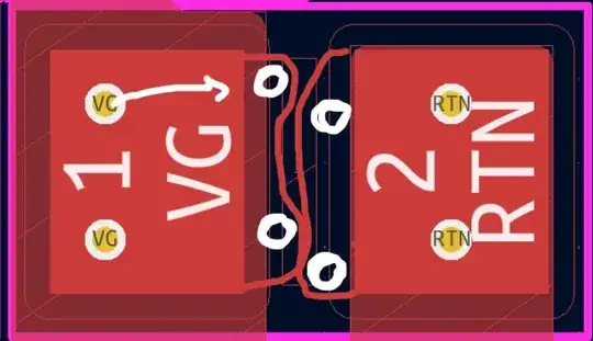
I see you're using via in pad, that will probably cost extra. Vias in the pads can suck your solder away so the cap isn't well soldered anymore. If you can have very small vias you can move them under the cap like this

enter image description here

bobflux
  • 77,207
  • 3
  • 91
  • 222
  • So, for R, G, B, separately : C.min = ( i.led.max • k.led.duty.max • n.ledPerScanline ) / ( v.ledBus.min • k.ripple.max • f.refresh • n.scanlines ). Why would worst case be a line of off then a line of on — wouldn't worst case be all lines nearly always on (duty just shy of 100%) so we're still pulsing and offering just enough time to energize back to full voltage? (With a half-cycle of off, wouldn't i.led be cut in half, since we're not discharging during that interval?) – kando Mar 21 '24 at 16:18
  • 1
    The chip lights up one line after the other, so the max current is indeed ( i.led.max • k.led.duty.max • n.ledPerScanline ). If all lines are on, it will draw this current almost constantly, whch results in maximum average current, and this is what you'd consider to size your power supply. But to size the capacitors, you need to consider maximum ripple current, which is the difference between maximum current (one line on) and minimum current (next line fully off). – bobflux Mar 21 '24 at 17:20
  • 1
    You have two cases. If your buck converter is fast enough and its transient response (incl. inductance of cabling) is fast enough to react at the line frequency and keep voltage steady, then you need less caps. If it is slower, the role of the caps is to average the pulsed current into a smoother current, so the buck can supply the average current. – bobflux Mar 21 '24 at 17:25
  • 1
    In the "all lines nearly always on" case you quote, the buck would be providing the required average current, which means the caps would not discharge. So in this case they do not have to recharge between lines as you seem to imply. In the one line on/one line off case, the buck would provide average current of 50% of the maximum, and the caps would charge with this current on dark lines, and on bright lines LED current would come 50/50 from the buck and the caps. So I guess I forgot a factor of 1/2 somewhere. – bobflux Mar 21 '24 at 17:28
  • I think I now understand: I was originally thinking, line current switches on or off --> parasitic inductances are triggered by change in current: v.L = L • di.L/dt --> v.L is a droop from the line, which triggers cap correction as detailed above. Always on with interrupt is worst case for parasitics — but what you are suggesting is that with large enough caps, the buck converter doesn't respond to a line switch at all, the caps do and the buck converter ideally finds a nearly-steady-state output re-energizing the caps, which has its own set of benefits. – kando Mar 21 '24 at 19:34
  • (What I understand less is how these caps will respond to any parasitics with much, much faster frequencies.) – kando Mar 21 '24 at 19:50
  • 1
    From the load's point of view, the caps and the buck are in parallel. This makes a current divider: load current is divided between the two in inverse proportion to their impedance at the frequency being considered. For HF, inductance dominates, so HF current runs in small local loops to the closest caps, which is good for EMI. At low frequency the buck has low impedance thanks to feedback, so it provides all the current. At the crossover frequency between the two you have to think about capacitance value and also ESR. – bobflux Mar 21 '24 at 20:06
  • Re: No electrolytic : Issue isn't the loss of battery during operation; rather, it's the loss of battery during long-term non-operation. Link – kando Mar 21 '24 at 22:48
  • 1
    Polymer caps leak a lot, aluminium much less. Have you run the numbers? These LEDs will use a lot of current, so you'll need a rather large battery. Will the caps leak more than the battery's self-discharge? I bet the off current of the LED driver will be a much worse problem. If you want very low current when off you'll need either buck converters with low off-state current, or switch the power to the whole thing with a MOSFET. – bobflux Mar 22 '24 at 00:09
  • I plan to array [3Sx2P] 21700s for battery power. The hand calcs work out. I'll have to return to considering MOSFET(s) as a global switch. (Originally I thought I could use the buck IC enables to cut everything.) If there's a switch upstream, maybe the electrolytics become a consideration again. – kando Mar 26 '24 at 14:09
  • 1
    If there's a BMS on your battery, you already got a global switch with the protection FETs. Anyway, with this size of battery, I don't think leakage through a disabled buck converter will be above self-discharge. 2P 21700 would be 10Ah, 100µA leakage is only 0.9Ah/year... – bobflux Mar 26 '24 at 17:55