21

Recently I purchased my very first scope and noticed something I'm really curious about its cause.

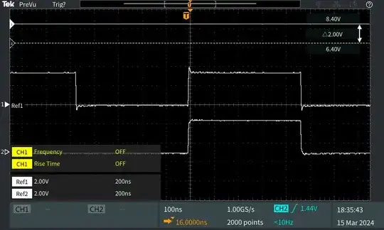
It's a 100 MHz scope, when I was testing to see the ringing of a 1 MHz clock signal with different values of series termination, using 100 MHz probe and 200 MHz shows quite different waveform:

enter image description here

Ref1 (top, 200 MHz probe) clearly showed the ringing exists while on Ref2 (bottom, 100 MHz probe) the signal already looked a little bit "not so sharp".

To my understanding, the bandwidth of scope and probe should be at least 5x of the signal frequency under test. In this case the signal is 1 MHz, which should be very easy for both 100 and 200 MHz probe to capture.

What is causing such huge difference?
Velvet
  • 4,299
  • 4
  • 14
  • 32
Jimmy.D
  • 549
  • 5
  • 12
  • A schematic of the circuit you were probing, and the capacitance specs of the probes, might make this easier to answer. – The Photon Mar 18 '24 at 15:20
  • 23
    Were the probes calibrated? – periblepsis Mar 18 '24 at 15:20
  • 3
    @ThePhoton I'm directly probing the SPI clk pin of a raspberry pi 4 so I'm afraid I'm not able to provide any schematics. The probes are Tektronix P2100 (100Mhz) and TPP0201 (200Mhz) – Jimmy.D Mar 18 '24 at 15:28
  • 7
    One or both of your probes probably need to be compensated--there'll be one or more holes on the end that plugs into the scope where you can turn potentiometers and/or variable capacitors to flatten the frequency response. There should be a procedure describing how to do this in the probes' manual. – Hearth Mar 18 '24 at 15:28
  • 3
    @periblepsis Yes, they are both calibrated using the scope's calibration signal. – Jimmy.D Mar 18 '24 at 15:28
  • @Hearth ok, now that so many comments asked about calibration, I started wondering if I did it right. I'll try to calibrate them again tomorrow when I get to my office. – Jimmy.D Mar 18 '24 at 15:30
  • 12
    Also note that 5x is only a rule of thumb; if you want to accurately reproduce the signal, the actual bandwidth required depends more on the signal rise and fall times, and should probably be at minimum about 0.4/tr (still a rule of thumb; the actual expression for bandwidth is pretty complicated). If your signal rise and fall times are very fast, there may be a real difference between the probes. – Hearth Mar 18 '24 at 15:36
  • 2
    The frequency, or rep-rate of your signal has nothing to do with what you're seeing & asking about. You will see that same phenomenon with a single edge signal, like a turn-on signal. It's related to the rise/fall time, or edge rate, of the signal. – SteveSh Mar 18 '24 at 15:56
  • 1
    Which probe settings you used? 1x or 10x? Did you calibrate the probes? – Justme Mar 18 '24 at 17:21
  • 1
    A lot of people talking about rise/fall rate, but it is because the fourier series approximation of of a square wave is basically infinite, meaning that the sharper the edge of the wave (rise rate) the higher frequency components that are needed to express it. – le3th4x0rbot Mar 19 '24 at 02:51
  • 1
    An ideal square wave contains frequencies that are very, very high. https://en.wikipedia.org/wiki/Square_wave – Steve Mar 19 '24 at 04:40
  • So just to close the discussion about probe compensation, I realized I did it wrong. I did not perform the compensation adjustment after switching the channels of the probes so there was a very slight error in the wave form. However even after carefully adjusting the compensation, resulted wave form is still the same. – Jimmy.D Mar 19 '24 at 18:29

2 Answers2

42

The signal under test is 1MHz, and as far as I can see, both probes are showing that signal correctly.

What you are looking to see on the edges, is less than 20ns. A signal with a period of 20ns has a bandwidth of 50MHz. If the ringing has the main harmonic with a period of 20ns, then that part of the signal has harmonics in the 50MHz band.

According to the rule of thumb that you mentioned, it means you need a probe of 250MHz to be able to see those changes clearly.

Saadat
  • 1,621
  • 8
  • 14
  • 16
    And OP's 'scope pictures show that, with the 100 MHz probe showing some rounding of the edges, while the 200 MHz probe shows what's really occurring. – SteveSh Mar 18 '24 at 15:58
  • 2
    "the edges, is less than 20ns. This means it has a bandwidth of more than 50MHz". It is not really as simple as BW=1/edge time. See @Attie's answer for a link and the correct formula. Your conclusion is correct, but your method not quite. – BrtH Mar 20 '24 at 13:37
40

A 1 MHz sine wave is not the same as a 1 MHz square wave - the most important part of what you're measuring and interested in here is actually the "edge rate", or the rise and fall times.

The screenshot you've provided doesn't show the edge in great detail, but it appears to have a ~3px rise time (3 pixels in the X direction), with a 50px graticule configured for 100ns /div ... that's approximately a ~6ns rise time. These edge times are typically measured between 10% and 90%, so rounding that down to ~4ns (or honestly, probably less), you'll be looking for equipment with a bandwidth in excess of 100 MHz (bandwidth * rise_time = 0.45, according to Tektronix).

The next thing to remember is that the rated bandwidth is generally the -3 dB point... which is where the signal has reduced to half power, or ~70.7% of the original signal's amplitude. (What is the significance of -3 dB?).

Finally, as has been mentioned in the comments, probes need to be compensated so they'll more accurately show you the signal you're probing. That "more accurately" part is incredibly important - simply inserting a probe into a circuit can have all sorts of implications, and there are many situations where your equipment may be lying to you, or at least not telling the whole truth - from horrific aliasing artifacts, to poor grounding, through to exactly what you're seeing here.

Attie
  • 1,661
  • 10
  • 12
  • 1
    Your answer also provides valuable knowledge to a newcomer like me. Unfortunately only one answer can be accepted, otherwise I would totally like to accept both you and Saadat's answer! – Jimmy.D Mar 19 '24 at 18:26