1

I'm currently in a state where I'm aware of the principal understanding when I'm confronted with a complex circuit, but I want more.

Especially when the circuit contains diodes the general method is to predict the voltage drop as for example 0.7 V, but that's not very detailed.

I've read about superposition and Thévenin elements to abstract a circuit, but they can't be applied to a semiconducter as it's not a linear element.

There can also be the case where the diode is not forward-biased as the voltage is only 0.4 V for example. So what are important methods to analyse the circuit deeper?

I hope my problem's clear, I'm not studying electrical engineering at a university, it's kind of a hobby.

ocrdu
  • 9,195
  • 22
  • 32
  • 42
olympus_mons
  • 139
  • 4
  • 1
    Please post an example. – Andy aka Feb 01 '24 at 16:30
  • As Andy says, we really cannot help unless you post an example and describe where you are stuck or have doubts. – StainlessSteelRat Feb 01 '24 at 16:45
  • Assume diode is conducting, then assume diode is not conducting, and see which assumption gives consistent results in the rest of the circuit. Note diode volt drop = 0.65ish volts is a lie to children that works for currents typically met in hobby circuits - 1uA to 10 mA. – Neil_UK Feb 01 '24 at 17:40
  • Like Neil_UK says, you can't think diodes as on/off devices. There are diodes that are fully off with 0.4V, there are diodes that are fully on with 0.4V, and diodes that are halfway between on and off with 0.4V, so you better look at the voltage vs current curves in the diode data sheet. And even then, it depends on temperature an manufacturing tolerances. Diodes leak in reverse too, some less and some more. Have you tried simulating these circuits? – Justme Feb 01 '24 at 17:55

3 Answers3

1

The question you're asking can be interpreted as, "how can I model circuits that contain non-linear elements"?

The answer is, you step up into the domain of circuit simulation, using a tool like Spice or its commercial derivatives such as PSpice ($$$), LT-Spice (free), MicroCap (free) and others.

Falstad uses Javascript, but ultimately does something like Spice.

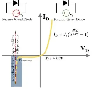
As for the specific case of a diode, the best-known model for it is the Schockley Diode Equation. Rather than reproduce it here, check out this answer: Current through a resistor with diode

A Spice model will use the Schockley equation, or a variant of it, to model the diode I-V characteristic. This characteristic will have four distinct regions:

  • reverse breakdown
  • reverse bias (leakage)
  • subthreshold forward bias before the "knee" (small current, but exponential vs. voltage as predicted by Schockley)
  • fully 'on' forward bias past the "knee" (large current, diode behaves like a low-value resistor)

enter image description here

from here: https://www.allaboutcircuits.com/technical-articles/understanding-i-v-curves-of-non-linear-devices/

The diode data sheet will always state the forward voltage drop (Vf) at a specific current. This is typically the midpoint of the "knee".

Related answer: Voltage across the diode

How does a Spice sim work? This (expensive) text will give some deep insight: https://books.google.com/books/about/Circuit_Simulation.html?id=oIQKPPijpe4C

And, an answer: How do Circuit Simulators actually work?

It's also possible to model a diode using forward voltage in series with bulk resistance, and obtain a reasonable computation-friendly result, as explained here.

hacktastical
  • 53,912
  • 2
  • 49
  • 152
0

In general, discrete and simple (one transistor or diode) non-linear devices aren't identical to each other, so they vary one to another, and vary their behavior with operating temperature, too.

They can be combined in special ways to gain more predictable behavior, but that is done by trading off their non-linearity to get there.

For example, Michael Wyatt's Cascode Peaking Current Source provides a high-speed current source that achieves a very low temperature coefficient by also taking advantage of the 3333 ppm/C aluminum resistors for 1st order compensation.

Or, more commonly, the use of global negative feedback to achieve predictable voltage gain in audio amplifiers.

It does, however, turn out that non-linear devices can be characterized. There was a period of time where companies spent a lot of money on semiconductor test systems. Tektronix used to have an entire division that was very active in this area. Once you have developed a number of important constants for a specific device, it's non-linear behavior can often be usefully predicted over a range of three to five orders of magnitude. (In one case, a Hamamatsu photodiode used in conjunction with thin film narrow band filter provided seven orders of predictable magnitude photo-response range when held at a fixed temperature.)

If a device is sufficiently characterized, more can be said. If just pulling them out of a box and using them, much less. When making many copies of a specific circuit, it may be prohibitively expensive to characterize each and every non-linear device and make adjustments to each circuit. An exception would be measurement instrumentation where calibration against national or global standard references is required. But in circuits where precision and accuracy isn't the goal (using an LED as an indicator light, for example), non-linear device variations should be managed to provide desired approximate behavior.

Keeping with the diode case, there are these ideas of ever-increasing dynamic ranges of utility:

  1. Assume or measure a fixed voltage drop at some specified operating current in the forward direction. For example, a RED LED might be assumed to have \$V_{_\text{FWD}}=2.0\:\text{V}\$ when operated at \$20\:\text{mA}\$. Or, its \$V_{_\text{FWD}}\$ could be quickly measured (characterized) by applying a current source of \$20\:\text{mA}\$ and measuring its \$V_{_\text{FWD}}\$.

    \$V_{_\text{D}}=V_{_\text{FWD}}\$. This model works at the specified operating current.

  2. Assume or measure a fixed voltage drop in the forward direction, with an assumed or measured series resistance. For example, a RED LED might be considered to be \$V_{_\text{FWD}}=1.6\:\text{V}\$ and \$R_{_\text{ON}}=20\:\Omega\$. At \$20\:\text{mA}\$, this works out to a \$2\:\text{V}\$ voltage drop, which is about right. This model is only useful over a small range of currents, say \$20\:\text{mA}\pm 10\:\text{mA}\$. Outside of that range, the model works poorly.

    To characterize it, measure the voltage across it using two different currents, say \$V_1=2.14\:\text{V}\$ with a current source set to \$I_1=25\:\text{mA}\$ and say \$V_2=1.87\:\text{V}\$ with a current source set to \$I_1=15\:\text{mA}\$. (Assuming actual operation will be around \$20\:\text{mA}\$.) Then find \$R_{_\text{ON}}=\frac{2.14\:\text{V}-1.87\:\text{V}}{25\:\text{mA}-15\:\text{mA}}=27\:\Omega\$ and \$V_{_\text{FWD}}=2.14\:\text{V}-27\:\Omega\cdot 25\:\text{mA}=1.465\:\text{V}\$.

    \$V_{_\text{D}}=V_{_\text{FWD}}+I_{_\text{D}}\cdot R_{_\text{ON}}\$. This model works over a small, specified range of operating currents.

  3. Assume or measure parameters for a simplified Shockley diode model. The model parameters here are the saturation current (\$I_{_\text{SAT}}\$, a fictitious y-axis intercept), an ideality or emission coefficient (\$\eta\$, often taken to be 1, ideally, but may be larger than 1), and the Ohmic resistance (\$R_{_\text{S}}\$.)

    To characterize this model requires at least three measurements taken at a single temperature of operation. One of these measurements must be taken at a current that is high enough so that \$R_{_\text{S}}\$ dominates and can be adduced from the data, but this should be pulsed for only a short time so that its temperature doesn't change. The other two measurements should be taken at one order of magnitude less current and then at two or three orders of magnitude still less.

    \$V_{_\text{D}}=\eta\cdot V_T \cdot \ln \left(1+\frac{I_{_\text{D}}}{I_{_\text{SAT}}}\right)+I_{_\text{D}}\cdot R_{_\text{S}}\$, where \$V_T=\frac{k\,\cdot\, T}{q}\$ is the thermal voltage and at room temperature will be near \$25\to26\:\text{mV}\$. This model works reasonably well over the included range of measurement currents, typically over a few orders of magnitude, so long as the temperature of operation isn't changed.

    However, \$I_{_\text{SAT}}\$ is very highly dependent upon temperature -- on the order of \$\propto T^3\$ -- and signed oppositely to \$V_T\$. So, for prediction over varying temperature requires still more measurement points to characterize a few more constants needed to develop \$I_{_\text{SAT}}\left(T\right)\$.

Obviously, apply given directions in educational settings and ignore what I wrote above if it differs. Otherwise, which of the above makes more practical sense will depend on circumstances.

The first two models listed above are relatively easy and closed solutions can be achieved using basic skills in algebra. The third model can be solved using a few steps of iteration and similar basic skills in algebra; or, directly, using the product-log function (branch-0 of the LambertW) and the ability to manipulate exponential functions.

The third model is important in order to understand log-amps, for example.
periblepsis
  • 8,575
  • 1
  • 4
  • 18
0

Understanding diode circuits by intuition

Begin with trying to find out what the purpose of the circuit is (switches signals, stabilizes voltage, etc.) to understand what function the diodes perform in it (electronic switches, voltage stabilizers, etc.)

Switching diode circuits

  • Ignore the forward voltage drop VF across the diode.

  • Think of the diode as a switch with two states - ON (zero resistance or short circuit) and OFF (infinite resistance or open circuit).

  • If the input source is an AC voltage source, consider the circuit in three states of the input voltage - zero, positive and negative.

  • For each of these states, replace the diodes with a short circuit (a piece of wire) or an open circuit ("nothing") depending on what the voltage across them is (is it greater or less than VF).

Autoswitching diode circuits

  • If two or more diodes (LEDs, Zeners, etc.) are connected in parallel, only the diode with the lowest forward voltage will be ON; the rest will be OFF.

  • If two or more voltage sources are connected "in parallel" through diodes to a common load, only the voltage source with the highest voltage will apply its voltage to the load; the rest sources will be OFF.

Decoupling diode circuits

  • If a single voltage source is connected through forward biased diodes to two or more loads, they are "decoupled" (there is no connection between the loads).

Diode voltage stabilizers

  • Think of the diodes as "voltage sources" and even temporarily replace them with such sources until you understand the circuit.

  • If you want to understand functionally how the diode keeps the voltage constant, think of it as a "dynamic resistor" that decreases its resistance when the current increases, and increases it when the current decreases (V = I.R = const).

  • You can replace strings of diodes and voltage sources in series with equivalent Zener diodes or voltage sources, and v.v.

"Shifting" diode circuits

  • Think of the diodes as floating "voltage sources" ("batteries") connected in series to the input voltage source. Replace them with batteries until you understand the circuit.

Non-linear diode circuits

Think of the diode as a "dynamic resistor" that changes its resistance so that the corresponding functional relationship is obtained:

  • If the voltage across the diode changes depending on the current through it, think of the diode as a log converter.

  • If the current through the diode changes depending on the voltage across it, think of the diode as an antilog converter.

Circuit fantasist
  • 16,664
  • 1
  • 19
  • 61