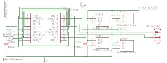
I am using a L298P motor driver on a custom circuit board to drive a DC motor. Since I am only using one motor I connected it in parallel like shown in the datasheet (IN1 and IN4 together, etc.).
My problem is that the output voltage is way too low, about 2-3 V with an input voltage of 7.4 V (Li-po battery). I would have expected about 5-6 V.
I have tried measuring the voltage without the motor; it is about 6 V.
I am using an Arduino Nano to control all this.
- VBATT: 7.4 V
- VCC: 5 V (not from the Arduino)
- SENA: Sens output connected to pin A1 on the Nano (should be tied to ground with a sens resistor, but I forgot that and just soldered pins 1, 2 and 3, 4 together)
- IN1: Connected to pin A3 on Nano
- IN2: Connected to pin A2 on Nano
- PWMA: Connected to pin D9 on Nano
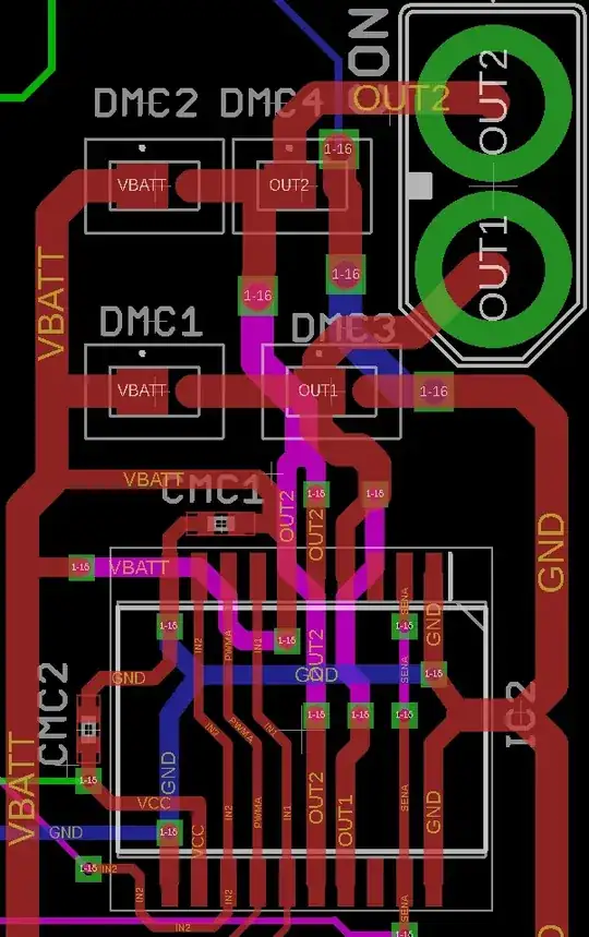
This is the part of the board where the motor controller is. Those vias are uncovered, to ensure the metal on the bottom does not short them. I have placed a piece of insulation tape there.
Code While I am pretty sure the code is not the issue, I am still going to include it. It simply uses two buttons to make the output voltage bigger or smaller.
// Programm um die Funktionsfähigkeit vom Motor und Treiber zu testen
// Start Button um Geschindigkeit erhöhen und Stop um zu veringern
// Motor Konnektoren
#define IN1 A3
#define IN2 A2
#define PWMA 9
#define SENA  A1
// Start und Stop Knöpfe
#define BT_STOP PD0
#define BT_START A7 // Reiner analog eingang; kein digitalRead() möglich!!!
bool richtung = true; // true => vorwärts; false => rückwärts
int motorGeschw = 0;
void setup() {
  Serial.begin(9600);
  pinMode(BT_STOP, INPUT);
  pinMode(BT_START, INPUT);
pinMode(SENA, INPUT); // WICHTIG!!! immer auf Input, weil sonst Strom über den Arduino abfliest
pinMode(IN1, OUTPUT);
  pinMode(IN2, OUTPUT);
  pinMode(PWMA, OUTPUT);
  if (richtung) {
    digitalWrite(IN1, LOW);
    digitalWrite(IN2, HIGH);
  }
  else{
    digitalWrite(IN1, HIGH);
    digitalWrite(IN2, LOW);
  }
}
void loop() {
  if (!analogRead(BT_START)) motorGeschw += 1; // Motorgeschwindigkeit um 1 erhöhen wenn Start Button gedrückt
  else if (!digitalRead(BT_STOP)) motorGeschw -= 1; // Motorgeschwindigkeit um 1 veringern wenn Stop Button gedrückt
motorGeschw = constrain(motorGeschw, 0, 255);
  analogWrite(PWMA, motorGeschw);
  Serial.println(motorGeschw);
}
If any of you have any idea what might be causing this issue, any help is greatly apreciated.
I have tested the motor with an Arduino Uno motor shield by Deek Robot (which uses the L298P). With that everything runs just fine and the voltages are as expected.

