0

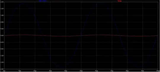
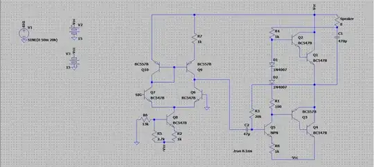
I want to design an amplifier to drive an 8 ohm speaker. I am using a differential amp as the first stage, and then a class AB amplifier (inspired by the one I found here class AB amplifier distortion). I need an output of 10v peak to peak but my output is around 3.9v peak to peak for an input of 50mv peak to peak at 20kHz.enter image description here enter image description here The output waveform is in blue, measured across the two ends of the 8 ohm speaker.
PS : Any good resources for learning analog electronics ? I am not very good at it. Besides Behzad Razavi's lectures.

Koustubh Jain
  • 293
  • 1
  • 8
  • If you bypass R7 then at least you have a reasonable mirror, but then the output from the diff amp is current-mode, not voltage, and that's a problem for the rest of the circuit (which I won't bother examining because of that.) I think there are too many items that need changing. – periblepsis Jan 15 '24 at 09:01
  • You specify $46:\text{dB}$ voltage gain, with power delivery. See here for a $60:\text{dB}$ voltage gain arrangement. Tweak just two resistors in the last schematic there ($R_{19}$ and $R_{39}$) to get the gain you need. (Your attempt at bootstrapping the speaker makes your $R_4$ look like a current source and that's a useful idea though I've no idea if you set it correctly. Regardless, it could be applied to the schematic I offered there.) – periblepsis Jan 15 '24 at 09:22
  • (I've seen a resistor on the emitter of the output BJT of a simple current mirror argued.) – greybeard Jan 15 '24 at 09:48

1 Answers1

2

Your Q5 doesn't have voltage gain, it's removed by having a big emitter resistor with no capacitive bypassing. R4 = R8 means "no gain". Make a web search "class ab transistor audio amp schematic" to see common practices.

Not asked, but having no emitter resistors for the output transistors is begging troubles (=a thermal runaway). Some resistor between the base and the emitter of the output transistors also is useful 1)for the same reason 2) for reducing the recovery slowness at transients by discharging the accumulated carriers from the base.

Prepare to meet the need of frequency compensation to prevent the oscillation when you have fixed the "too little gain" problem and start to need feedback from output to the differential amp to stabilize the total gain - and the output DC voltage, too, when you change the circuit fully DC coupled.

unawriter
  • 139
  • 3