The answer here is to remember the function of the pins. The pins near the center of the device are all inputs. They aren't driving a signal back to the controller and as such don't need a decoupling cap to handle the io driver switching currents. Instead you just need caps to manage the internal ic switching and return back to the controller driver.
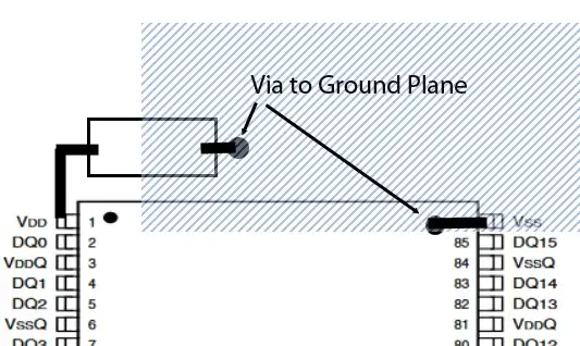
The same for the corner vdd and vss pins. They are providing power and return for the internal logic. For all vdd and vss pins you should place a cap at each pin. You could place one underneath but personally I would not share the cap but instead put one by the vdd pin and another by the vss pin and so on. You can then keep traces to vias and to planes short.
The vddq and vssq pins are your data io driver power pins. These need to provide a low impedance path for the power to the data drivers, driving back to the host.
You will note that there are two vssq and two vddq pins on each side.
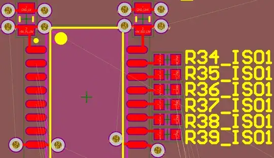
Here you should place the caps between each vddq /vssq pair. To avoid interfering with the dq fan out, you could place the caps underneath the sdram, and place vias at the pins, straight down to the caps, tied to the respective vddq and vss (gnd) plane.
I would use 16 caps. You could get away with 12 if you share one between each vdd/vss pair. Optimal placement for caps would be top side, next to the sdram. If space is tight, then place on the rear under the parts pins, especially if it is a 1.6mm board.


