2

The following is a snippet from the book Design of Analog CMOS Integrated Circuits

enter image description here

Here is what I thought.
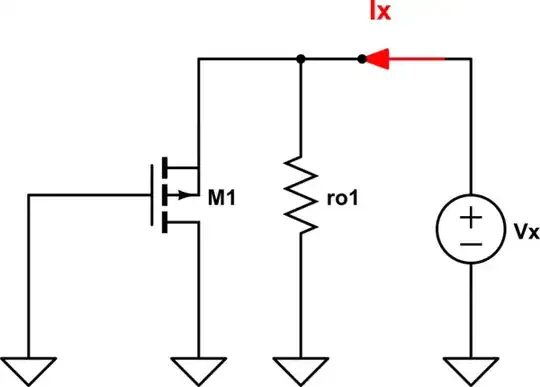
enter image description here

$$V_1 = 0-V_x $$

$$V_{bs1} = 0 - V_{s1}$$

$$V_{s1} = I_x r_{o1}$$
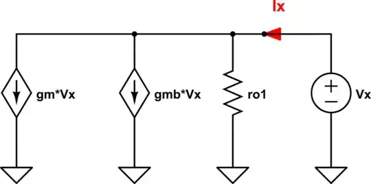
According to KCL.

$$ g_{m1} V_1 + g_{mb1} V_{bs1} = I_x $$

We can use those equation we got earlier to replace \$V_{1}, V_{bs1}\$.

Finally we can derive the equation.

$$R_{eq} = \frac{V_x} {I_x} = - \frac{1 + g_{mb1} r_{o1}} {g_{m1}}$$.

However, the book gave the following.

$$R_{eq} = r_{o1} \parallel \frac{1}{g_{mb1}} \parallel \frac{1}{g_{m1}}$$

winny
  • 14,707
  • 6
  • 46
  • 66
kile
  • 798
  • 2
  • 11

1 Answers1

2

Your equivalent circuit is wrong. Your job is to find \$R_{eq}\$. This \$R_{eq}\$ is the small-signal resistance seen from \$M_1\$ source terminal when we are looking into the source terminal when \$V_{IN} = 0\$.

schematic

simulate this circuit – Schematic created using CircuitLab

\$R_{eq} = \frac{V_X}{I_X}\$

Thus, the equivalent small-signal model will look like this:

schematic

simulate this circuit

And to find the thevenin voltage \$V_{TH} = V_{in,eq}\$. You need to find the voltage gain of this circuit:

schematic

simulate this circuit

$$V_{out} = \biggl( g_{m1} (V_{in} - V_{out}) - g_{mb1} V_{out}) \biggl) r_{o1}$$

$$\Rightarrow V_{out} = \frac{g_{m1} r_{o1}} {1+(g_{m1} + g_{mb1}) r_{o1}} V_{in}$$

$$\Rightarrow V_{th} = V_{out} = \frac{g_{m1} r_{o1}} {1+(g_{m1} + g_{mb1}) r_{o1}} V_{in}$$

kile
  • 798
  • 2
  • 11
G36
  • 14,576
  • 1
  • 20
  • 36