Below are two circuits that build on some of the previously posted ideas but also satisfies most of the parameters of the original request.
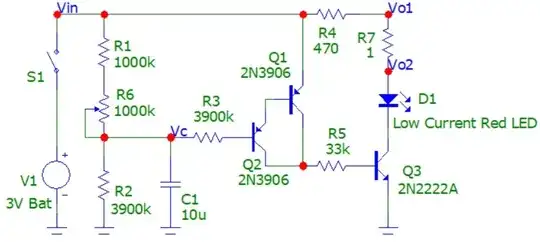
The first circuit takes advantage of the slow charging of a cap and the high gain of a PNP Darlington pair. When S1 closes C1 slowly begins charging via R1, R6, and R3. The current coming from R3 initially turns on Q1 & Q2. An amplified current then flows through the collectors of Q1 & Q2 turning on Q3 which lights the LED, (D1 is a low current Red LED that operates at 2 ma). As the voltage on C1 continues to rise it reaches a point where the Q1 Q2 transistors begin to cut off. With the very low charging current the full cut off point for the transistors as well as the LED comes about very slowly.
The timing in this circuit will be susceptible to the uncontrolled gain and other parameter of the Darlington pair so there would likely be a good amount of variability from that, in addition C1 will likely have a 10% tolerance or greater, so a potentiometer (R6) can be used for adjustments to make up for these variations. R1 and R6 could actually be a single potentiometer. The 1 ohm resistor R7 is not required and is only included here to graph the LED current.
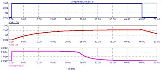
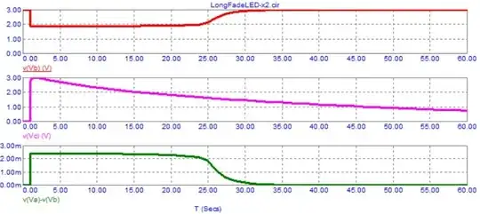
The third graph (in each group) shows the voltage across the 1 ohm resistor (and is a 1:1 equivalent for showing the LED current).
When S1 re-opens the circuit needs time to discharge, if S1 is closed again before C1 is fully discharge the timing will be reduced.
Other than the battery if all components were SMT types the whole circuit might only take up an area about the size of a 3 V lithium coin cell.
.
.
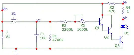
The second circuit operates a little differently than the first and makes use of a momentary NO push button (S1). Note that in some greeting cards a normally open switch will have a thin insulator between two finger contacts, opening the card slides the insulator out allowing the contact. To simulate a push button it may be possible to have a only a small hole in the thin insulator positioned exactly where the contact points pass. Then as the card is opened the switch briefly closes but is then re-opened as the card opens further.
When this circuit receives the brief switch closure C1 is quickly charged. When the switch re-opens C1 begins to slowly discharge via R1, R2, and R5. The small current through R2 & R5 turns on Q1 & Q2 (in a Darlington arrangement), Q2's emitter current then turns on Q3 that lights the (low current Red) LED. As in the first circuit the 1 ohm resistor is included only to graph the LED current and the pot allows for potential adjustment. Also as in the first circuit C1 will need to fully discharge before the same timing can be realized on the next card opening. (Actually with the switch described above the LED will flash once again as the card is closed).
.
In both circuits the use of very small currents allow the use of a smaller cap values and obviously a smaller body size.
.
.


I know that newer timers use much less power, but I don't have the skill to re-calculate the example so I can get the correct parts...
– BirdsInMyBrain Oct 27 '23 at 01:05