Your circuit will operate in the linear region and this means that the gate-source voltage will be moderate to low in value and nowhere near the value to obtain lowest \$R_{DS(on)}\$ (a parameter associated with switching applications) and, unfortunately you can't use it to calculate power dissipation. However, you can use your simulator to calculate the true power dissipated namely \$I_D \times V_{DS}\$.
This always equates to the MOSFET power dissipated (although it doesn't account for the small amount of power used by the gate). However, yours is a linear application so the gate power is largely irrelevant.
You should also be aware of thermal runaway problems with MOSFETs in linear applications and try and focus on choosing a MOSFET that is designed to be less problematic under these circumstances. IXYS make a few parts that are specified for linear applications. Be also aware that several parallel MOSFETs with individual op-amp control is the way to go.
Treat each parallel arrangement of MOSFET and control op-amp separate i.e. don't try and share the same current sense resistor.
what is the power rating for the MOSFET
Data sheets tell you a figure on their front page about power rating but this won't help you. The figure quoted is for switching applications i.e. it is a "summary" value for short pulses that counts for nothing in your type of linear application. Hence, a single data sheet value for the power rating will not help.
You have to dig deeper and look at the safe operating area curve in the data sheet. Then you look for the curve that implies continuous operation. In your previous question on this subject I showed this graph for an IGBT and, we can use that to demonstrate what I mean: -
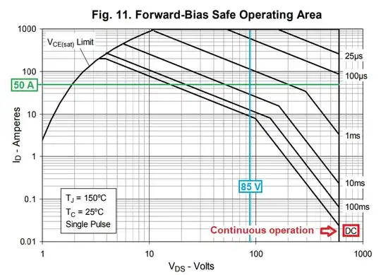
Previously, your requirement was for 50 amps at 85 volts and that meant that the peak power is 4.25 kW but, where those lines cross on the graph, the device can only sustain this power for 3 or 4 ms maximum.
So, you look at the DC curve (continuous operation) and see that the device can only sustain about 8 amps maximum when \$V_{DS}\$ is 85 volts. That's a power of 680 watts and not 4.25 kW.
This implies to me that the minimum number of parallel devices needed is seven i.e. 7 devices with their associated current sense resistors and op-amps. Of course this was for an IGBT but, it won't be much different when using MOSFETs. For your new requirement (circa 6 kW) you might be looking at ten parallel circuits and, if you choose smaller devices than the IGBT I targeted in the previous question, you might be looking at 12 to 15 parallel circuits.

