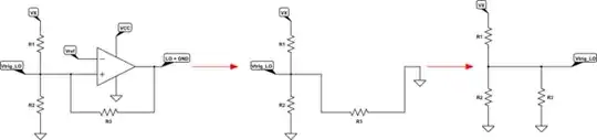
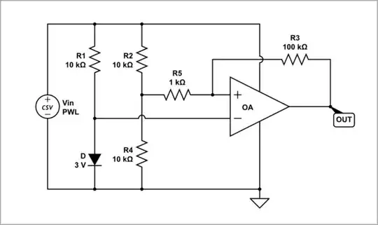
This is how I would approach the problem. Below is the circuit drawn with nodes Z and X, where Z has fixed reference potential \$V_Z\$, and X has potential \$V_X\$ that is a function of both output \$V_{OUT}\$ and the supply \$V_{DC}\$:
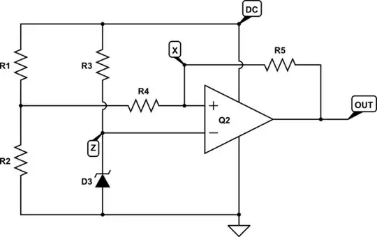
simulate this circuit – Schematic created using CircuitLab
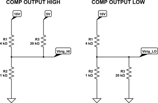
You have two conditions to consider, output high, \$V_{OUT} = V_{DC}\$, and low, \$V_{OUT} = 0V\$. In the former case, we have a network of resistances connected as shown below left, and the latter situation on the right:
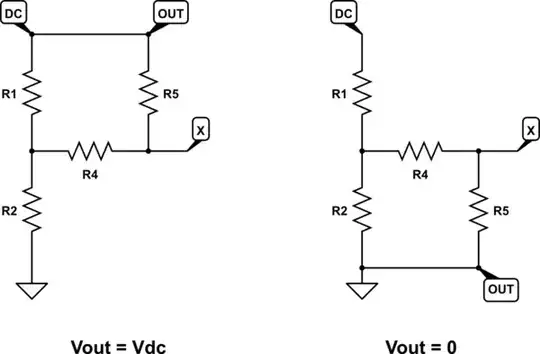
simulate this circuit
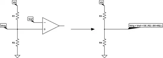
The algebra is easier if we treat the supply DC and resistors R1 and R2 as their Thevenin equivalent:
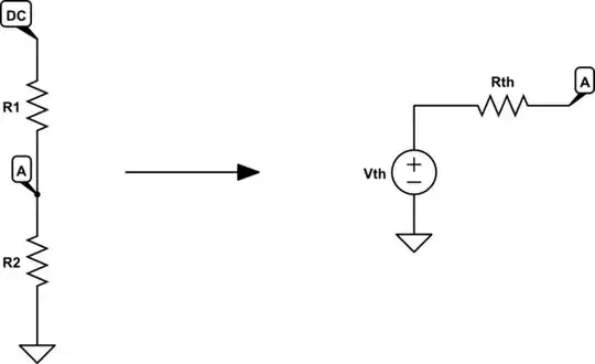
simulate this circuit
where:
$$ V_{TH} = V_{DC}\frac{R_2}{R_1+R_2} $$
$$ R_{TH} = R_1 \parallel R_2 = \frac{R_1R_2}{R_1 + R_2} $$
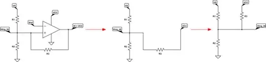
The resistor networks in each situation (high and low output) are therefore equivalent to these:
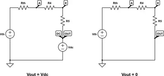
simulate this circuit
These are simple resistor potential dividers, the only difference between the two being the presence/absence of the voltage source \$V_{DC}\$. The potentials at X are trivial to write:
$$ V_{X(H)} = V_{DC} + (V_{TH} - V_{DC})\frac{R_5}{R_4 + R_5 + R_{TH}} $$
$$ V_{X(L)} = V_{TH}\frac{R_5}{R_4 + R_5 + R_{TH}} $$
You may have noticed that R4 is redundant. It's effectively in series with the other two resistances R5 and Rth. You can obtain exactly the same values for \$V_X\$, in both states, by removing it altogether, and adjusting Rth and/or R5 to compensate. I won't do that here, it's just a heads-up.
Now you can substitute back in the expressions for \$V_{TH}\$ and \$R_{TH}\$ from before. The last step is to equate \$V_{X(H)} = V_Z\$ and \$V_{X(L)} = V_Z\$, which I think you can handle from here. You should end up with expressions for \$V_{X(H)}\$ and \$V_{X(L)}\$ in terms of only the resistances and \$V_{DC}\$.
Update 1 - choosing resistances
Here's an answer I wrote about this, which will help to choose an order of magnitude for the resistances in the circuit.
If you start by specifying explicit potentials for the upper and lower switching thresholds, say \$V_{DC}=8V\$ and \$V_{DC}=6V\$, and the zener voltage, say \$V_Z=4.7V\$, you obtain two simultaneous equations that can be rearranged to yield any two of the resistances. The problem is that there are four resistances to find, and only two simultaneous equations. That's because there are infinitely many solutions for those resistances that would satisfy the conditions described by the equations.
Note: As I mentioned before, I consider \$R_4\$ and \$R_{TH}\$ to be a single resistance, and it will greatly simplify things if you set \$R_4 = 0\Omega\$. You could always re-introduce \$R_4\$ again later, and adjust \$R_{TH}\$ to compensate, but I see no reason to do that. \$R_4\$ is completely redundant here.
It seems impossible to solve, but all you need to do is randomly (well, not randomly, follow the guidelines from the linked answer above) select values for any two of them, say \$R_4 = 10k\Omega\$ and \$R_5=100k\Omega\$, and then solve for the other two.
At this stage it doesn't matter whether you guessed those resistances correctly or not, because the ratio of the resistances will be the same for all solutions. That is, if you multiply all the resistances by the same factor (say 2, or 0.5) they will still be valid solutions, and the thresholds remain the same. This is due to the linear nature of the system.
So if, for example, when you solve the system of equations using some randomly chosen value of R4 and R5 (or any of them), but you find the resulting resistances to be on the low side, then double them all (or multiply them all by whatever factor would yield more appropriate values), and they will produce the same voltages everywhere. This trick wouldn't work if the equations weren't linear, but in this case they are.
Update 2 - a walkthrough
$$ V_{X(H)} = V_{DC} + (V_{TH} - V_{DC})\frac{R_5}{R_4 + R_5 + R_{TH}} $$
$$ V_{X(L)} = V_{TH}\frac{R_5}{R_4 + R_5 + R_{TH}} $$
The Thevenin equivalencies:
$$ V_{TH} = V_{DC}\frac{R_2}{R_1+R_2} $$
$$ R_{TH} = \frac{R_1R_2}{R_1 + R_2} $$
Combining these:
$$
\begin{aligned}
V_{X(H)} &= V_{DC} + \left( V_{DC}\frac{R_2}{R_1+R_2} - V_{DC} \right) \frac{R_5}{R_4 + R_5 + \frac{R_1R_2}{R_1 + R_2}} \\ \\
&= V_{DC} \left( 1 - \frac{R_1R_5}{(R_4+R_5)(R_1+R_2)+R_1R_2} \right) \\ \\
\\ \\
V_{X(L)} &= V_{DC} \left( \frac{R_2}{R_1+R_2} \right) \left( \frac{R_5}{R_4 + R_5 + \frac{R_1R_2}{R_1 + R_2}} \right) \\ \\
&= V_{DC} \frac{R_2R_5}{(R_4+R_5)(R_1+R_2)+R_1R_2} \\ \\
\end{aligned}
$$
We are going to specify values of \$V_{DC}\$ where we intend switching to occur, corresponding to when \$V_X=V_Z\$ in each case, so substitute \$V_X\$ with \$V_Z\$:
Note: counter-intuitively, the upper threshold \$V_{DC(MAX)}\$ occurs when the output is low, and vice versa.
When the output is high:
$$
\begin{aligned}
V_Z &= V_{DC(MIN)} \left( 1 - \frac{R_1R_5}{(R_4+R_5)(R_1+R_2)+R_1R_2} \right) \\ \\
V_{DC(MIN)} &= V_Z \frac{(R_4+R_5)(R_1+R_2)+R_1R_2}{(R_4+R_5)(R_1+R_2)+R_1R_2-R_1R_5} \\ \\
\end{aligned}
$$
When the output is low:
$$
\begin{aligned}
V_Z &= V_{DC(MAX)} \frac{R_2R_5}{(R_4+R_5)(R_1+R_2)+R_1R_2} \\ \\
V_{DC(MAX)} &= V_Z \frac{(R_4+R_5)(R_1+R_2)+R_1R_2}{R_2R_5} \\ \\
\end{aligned}
$$
These don't look much like the equations quoted in your question. I don't want to spend ages reconciling your equations with mine. In any case, mine here are correct.
Since both of these share the same rather complex term, I'll write them like this:
$$
\begin{aligned}
K &= (R_4+R_5)(R_1+R_2)+R_1R_2 \\ \\
V_{DC(MIN)} &= V_Z \frac{K}{K-R_1R_5} \\ \\
V_{DC(MAX)} &= V_Z \frac{K}{R_2R_5} \\ \\
\end{aligned}
$$
Let's establish some targets. These are some example characteristics I am aiming for, using a 4.7V zener diode:
$$
\begin{aligned}
V_Z &= 4.7V \\ \\
V_{DC(MIN)} &= 6V \\ \\
V_{DC(MAX)} &= 8V \\ \\
\end{aligned}
$$
Unfortunately, here's where things get difficult, because to solve these two equations with four unknown resistances, requires us to "guess" two of them. If we choose unwisely the equations could yield a solution for the other two with negative resistances. Algebraically the solution would still be valid, but physically impossible to build.
Intuitively, I see that \$R_5\$ and \$R_4\$ together are responsible for hysteresis, the "gap" between the two thresholds. \$R_1\$ and \$R_2\$ on the other hand control the "midpoint" potential. We would have to take great care when setting the midpoint, which would be algebraically complicated, so I won't specify \$R_1\$ or \$R_2\$. I'd rather let the algebra we've already established deal with that.
Instead, I'll try choosing arbitrary values for \$R_4\$ and \$R_5\$. I am sure that \$R_4=0\$ will work just fine (which I recommend), but in the interest of keeping \$R_4\$ in this design, I'm going to set it to be much smaller than \$R_5\$, and non-zero. If \$R_4\$ is too large compared with \$R_5\$, we may inadvertently make it impossible for \$V_X\$ to ever equal \$V_Z\$, which would yield negative \$R_1\$ and/or \$R_2\$ in the solution.
$$
\begin{aligned}
R_4 &= 10\Omega \\ \\
R_5 &= 100\Omega \\ \\
\end{aligned}
$$
Clearly, those values are too small, but they keep the calculations simple, and permit me to show you later on how we can adjust and correct them.
Plug these values into the simultaneous equations from above:
$$
\begin{aligned}
K &= (R_4+R_5)(R_1+R_2)+R_1R_2 \\ \\
&= 110(R_1+R_2)+R_1R_2 \\ \\
\end{aligned}
$$
$$
\begin{aligned}
V_{DC(MIN)} &= V_Z \frac{K}{K-R_1R_5} \\ \\
6 &= 4.7 \frac{K}{K-100R_1} \\ \\
R_1 &= \frac{1.3}{600}K \\ \\
\end{aligned}
$$
$$
\begin{aligned}
V_{DC(MAX)} &= V_Z \frac{K}{R_2R_5} \\ \\
8 &= 4.7 \frac{K}{100R_2} \\ \\
R_2 &= \frac{4.7}{800}K \\ \\
\end{aligned}
$$
To solve these, substitute the expressions for \$R_1\$ and \$R_2\$ into the equation for \$K\$, and solve for \$K\$. Then use that value for \$K\$ to evaluate \$R_1\$ and \$R_2\$. We finally have all resistances:
$$
\begin{aligned}
R_1 &= 19.57\Omega \\ \\
R_2 &= 53.07\Omega \\ \\
R_4 &= 10\Omega \\ \\
R_5 &= 100\Omega \\ \\
\end{aligned}
$$
These are far too small, and will draw too much current from the supply and op-amp output. With these equations all being linear, we can simply scale all resistances by the same factor, without changing any voltages anywhere.
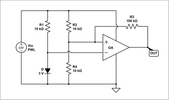
This means you can find a factor that will adjust any one of the resistances to become any value you choose, and when you scale all the resistances by that same factor, circuit behaviour doesn't change. I will multiply them all by 1000, to get resistances in the tens of kilohms:
$$
\begin{aligned}
R_1 &= 19.57k\Omega \\ \\
R_2 &= 53.07k\Omega \\ \\
R_4 &= 10k\Omega \\ \\
R_5 &= 100k\Omega \\ \\
\end{aligned}
$$
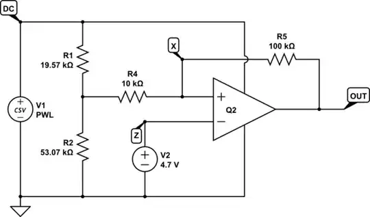
simulate this circuit
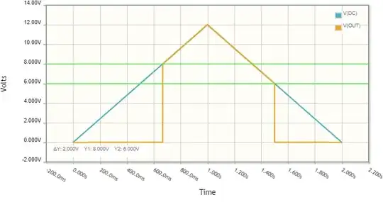
Here's a plot of \$V_{DC}\$ and \$V_{OUT}\$ as I sweep V1 from 0V to 12V and back to 0V. As you can see, the output rises when \$V_{DC}=8V\$, and falls again when \$V_{DC}=6V\$:


