1

While my background is EE, I've mostly worked as a firmware person. I'm designing a product that should reset about 5 seconds after being placed onto a charger. The delay is to allow time for data to be written to flash if need be.

I'm working with the BG77 part, which has an input RESET_N, which triggers the reset after 2 seconds of being asserted. The waveform for this: enter image description here
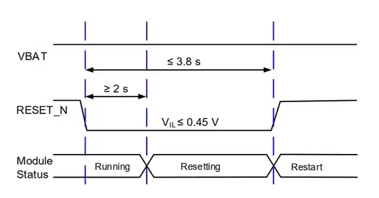
Ideally the reset circuitry will be powered directly from the charger (the product is battery-powered, so any power we can save is helpful). I've broken the problem down into two stages: the delay, and the reset. I desire a signal like this:

Desired signal

My initial idea was two 555 timers: one for the delay and one for the RESET_N assertion. I came up with this: 555 Timer Schematic

This simulated correctly with PSpice for TI: enter image description here
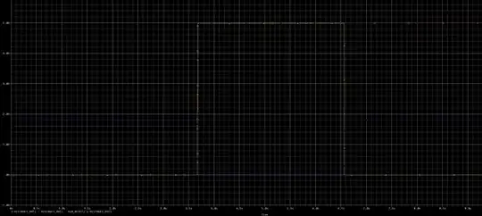
However, in hardware the timing is off by a lot (yellow = RESET_N, green = VUSB, purple = output of delay circuit): Scope of the hardware circuit

  1. The delay is about 1 second, not 3 as expected
  2. The reset pulse is just over 1 second, not 2.9 seconds as expected.

I'm also interested in using a voltage supervisor for this, although I've struggled a bit with this as it needs a voltage input to drive the output logic.

I've gotten quite frustrated with this! I'd love to fix this and have it behind me for the next spin of the board, but I keep tying myself into knots on getting this right - it seems so simple and yet...

In any case, I'd appreciate any insights into what I'm doing wrong on this. If there's a way to make the 555 circuit approach work with a simple change, I'd prefer that at this point, but otherwise I am open to just about anything.

Cheers, Jonathan

Jonathan
  • 11
  • 1
  • There's a lot of nice hardware built into 50 cent, SOT-23-6 packaged MCUs. If you don't mind adding a toolchain, anyway. That would be V_USB powered, too. But you want something with (CMOS?) 555's? Or discrete? (The timing doesn't seem like it needs great precision, only that it must meet some minimums. So discrete is possible, but will likely require one or more FETs for such long durations.) I'm also getting the clear message that you want something that will work when built. Not only in simulation. A worry I'd have (and why an MCU is nice) has to do with all the possible power-up scenarios. – periblepsis Aug 08 '23 at 00:32
  • For example, what should happen when flicking and rocking the USB connector back and forth in order to make semi-random connection/disconnection events with a lot of nasty-looking choppy stuff on V_USB? How must this respond to all manner of ugliness? Do you expect nice and pretty lines? Or plan to de-bounce the V_USB? All this is why I'd reach for an MCU with a decent BOR. – periblepsis Aug 08 '23 at 00:38
  • There is a fairly common circuit that can do this with one 555. The idea is that there is an R-C delay between power being applied and a Trigger event (as you have, but with some extra parts), and then the 555 produces the output pulse. It appears that the triggering of the 2nd 555 is incorrect. More later. – AnalogKid Aug 08 '23 at 00:49
  • 1
  • @periblepsis the FW side of me would definitely do this, but for this particular product and setup, it really seems like overkill. This product is in a regulated field, and having a hardware-only reset is the most easily justified thing to do. – Jonathan Aug 08 '23 at 01:15
  • @AnalogKid I agree, that was sort of what I started by thinking, but ultimately have gotten myself twisted into knots trying to get all of the parameters right. Something like Dave Tweed mentioned may be helpful, I will have to look at it more closely. The thing I'm frustrated with is why my simulation doesn't match reality, which has me a bit scared of trusting anything w/the 555 without a deeper understanding of all the parts. – Jonathan Aug 08 '23 at 01:19
  • Do you really, absolutely, positively, have to perform the reset in hardware? Couldn't you just tie Vusb into whatever MCU you presumably already have in your device and then have it do the timing & reset in firmware? – brhans Aug 08 '23 at 01:19
  • @periblepsis I'm sorry for the double-comment. I meant to respond more to your question about my requirements. My preference would be to have the initial "delay" portion of the circuit reset if the VUSB is detached during that period of time. That was the initial idea behind the resistors and diodes in the left side of the delay circuit, effectively stop the initial delay so that on reconnect, the delay begins again. – Jonathan Aug 08 '23 at 01:22
  • @brhans it's a very nice way to be able to very clearly show that regardless of any bad state the software could get itself into, it will absolutely, positively be reset. One could imagine bad firmware causing even a watchdog not to work as expected. VUSB is indeed already tied into the MCU so that we get the interrupt to say a reset is coming, which should trigger a few cleanup tasks. But the idea is that even if the firmware is good and borked, that reset will happen. – Jonathan Aug 08 '23 at 01:25
  • @Jonathan You don't want to power from battery for good reason. Just thinking only about the 2 s nRESET going low, I'm tempted to say that it should be arranged so that it physically *cannot* be pulled low without V_USB above some threshold for some time (energy stored in an inductor for example.) Or can you tolerate the occasional false nRESET and don't need a guarantee based upon laws of physics? – periblepsis Aug 08 '23 at 05:47
  • @Jonathan Here's my *mad scientist* method. Physics here ensures that false triggers are ... very unlikely. The edges can be sharpened up a bit with some extra circuitry, too. Bullet-proof. What's there to complain about? ;) – periblepsis Aug 08 '23 at 06:08
  • 1
    Is the focus of your question how to improve the simulation, or just to get a working circuit? I'm inclined to concur with Dave Tweed's suggestion unless said otherwise. For my part, I would suggest something to do with a reset generator / power monitor IC, perhaps cascading two in such a way as to generate the desired pulse. Or a window comparator and a single RC time constant. There's nearly infinite space for various hardware implementations here. – Tim Williams Aug 08 '23 at 12:06
  • 1
    @periblepsis thank you for the proof of concept - it looks great for the simulation :) – Jonathan Aug 08 '23 at 12:19
  • 1
    @TimWilliams That's what I'll look into today - that does seem like the right approach. In general I'm looking to get a working circuit, within reason (i.e., cost, board space, power usage). I'm not sure the right way to respond to comments - apologies if I'm adding noise. – Jonathan Aug 08 '23 at 12:21
  • @Jonathan I'll add my 2 cents worth of weight to Dave's pointer and Tim's added comments. (But I do still have a fondness of many kgs of rock solid, bullet-proof inductances. It's physics-guaranteed. Even a nearby (but not direct hit) lightning strike may find trouble getting through it. ;) -- assuming the V_USB survives of course.) When you do work out a design you like, why not add it here as an answer? (You can even select it.) – periblepsis Aug 09 '23 at 01:53

0 Answers0