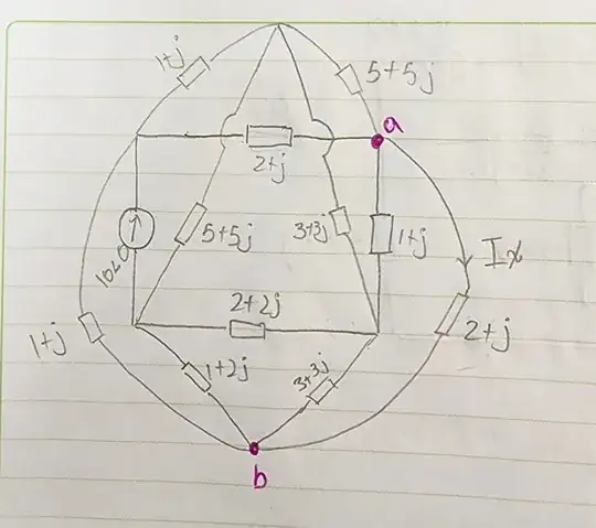
They ask me to find a way to calculate the voltage between a and b but without using the node method, only the mesh method

-
please add a clear, answerable question to your post... as it stands, there is no question – jsotola Jun 14 '23 at 20:30
-
Ricardo, do you want me to show you a very simple mathematical way to identify all of the appropriate mesh current loops you need to apply to any complex circuit? There's a nice, simple method using matrices that you use to just plug things in and it will tell you every loop you need analyze -- no more, no less -- always exactly the right number and the right ones. Let me know. – periblepsis Jun 14 '23 at 21:54
-
1This circuit is planar. You've just drawn it in a nonplanar embedding. – Hearth Jun 15 '23 at 01:46
2 Answers
Why do you think your graph is non-planar?
- Planar graph: A graph is planar if it can be drawn on a plane so that no two edges have an intersection that isn't a node. This will be true if and only if it can be drawn on a sphere without intersections.
I can visualize your example on a sphere or a plane, without intersections.
Note: I enjoyed Advanced Series In Electrical and Computer Engineering -- Vol 5, Graph Theory and It's Engineering Applications, by Wai-Kai Chen, 1997 and also recommend Gilbert Strang's Introduction to Linear Algebra, 5th edition.
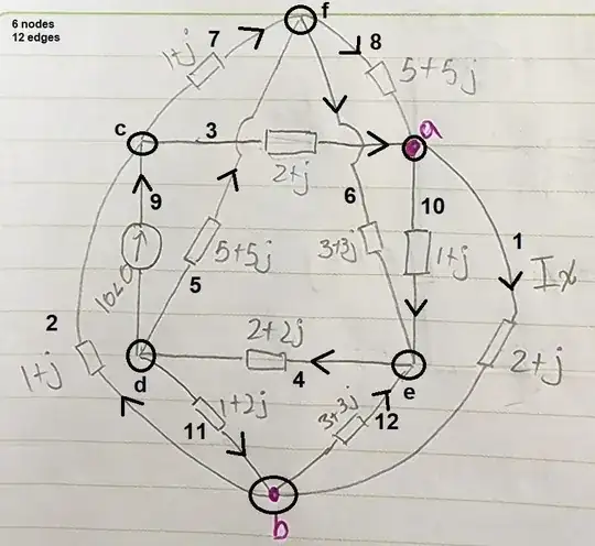
Skipping to the point, let me show how I arranged a directed graph of your circuit:
The matrix representing the above digraph is:
$$\begin{align*} \begin{matrix} \fbox{A}&N_a&N_b&N_c&N_d&N_e&N_f\\ \hline E_1: &\hfill -1&\hfill 1&\hfill 0&\hfill 0&\hfill 0&\hfill 0\\ E_2: &\hfill 0&\hfill -1&\hfill 1&\hfill 0&\hfill 0&\hfill 0\\ E_3: &\hfill 1&\hfill 0&\hfill -1&\hfill 0&\hfill 0&\hfill 0\\ E_4: &\hfill 0&\hfill 0&\hfill 0&\hfill 1&\hfill -1&\hfill 0\\ E_5: &\hfill 0&\hfill 0&\hfill 0&\hfill -1&\hfill 0&\hfill 1\\ E_6: &\hfill 0&\hfill 0&\hfill 0&\hfill 0&\hfill 1&\hfill -1\\ E_7: &\hfill 0&\hfill 0&\hfill -1&\hfill 0&\hfill 0&\hfill 1\\ E_8: &\hfill 1&\hfill 0&\hfill 0&\hfill 0&\hfill 0&\hfill -1\\ E_9: &\hfill 0&\hfill 0&\hfill 1&\hfill -1&\hfill 0&\hfill 0\\ E_{10}:&\hfill -1&\hfill 0&\hfill 0&\hfill 0&\hfill 1&\hfill 0\\ E_{11}:&\hfill 0&\hfill 1&\hfill 0&\hfill -1&\hfill 0&\hfill 0\\ E_{12}:&\hfill 0&\hfill -1&\hfill 0&\hfill 0&\hfill 1&\hfill 0 \end{matrix} \end{align*}$$
(There's a -1 where an edge points away from a node and a 1 where an arrow points into a node.)
The needed meshes can be worked out by simply finding the nullspace of the transpose of the above matrix. That's it. It may not select the loops you'd prefer. But it will select a set required to solve any valid circuit problem.
The reason this method works is because Ohm's law is in the columnspace and the left-nullspace (also orthogonal to the columnspace) represents those vectors that the KVL must go to the origin (zero.) In short, the mesh loops around which Ohm's law sums to zero. (It's fundamental to the geometry of these mappings of one space to another.)
In this case, taking A to be the above matrix, the nullspace vectors from its transpose (which is how the left-nullspace is defined) are:
$$\text{Nul}\: A^T=\left\{ \pmatrix{\phantom{-1}\\1\\1\\1\\0\\0\\0\\0\\0\\0\\0\\0\\0\\\phantom{-1}}, \pmatrix{\phantom{-1}\\0\\0\\0\\1\\1\\1\\0\\0\\0\\0\\0\\0\\\phantom{-1}}, \pmatrix{\phantom{-1}\\1\\1\\0\\0\\0\\0\\1\\1\\0\\0\\0\\0\\\phantom{-1}}, \pmatrix{\phantom{-1}\\0\\0\\0\\0\\-1\\0\\1\\0\\1\\0\\0\\0\\\phantom{-1}}, \pmatrix{\phantom{-1}\\-1\\-1\\0\\1\\1\\0\\-1\\0\\0\\1\\0\\0\\\phantom{-1}}, \pmatrix{\phantom{-1}\\0\\1\\0\\0\\-1\\0\\1\\0\\0\\0\\1\\0\\\phantom{-1}}, \pmatrix{\phantom{-1}\\0\\-1\\0\\1\\1\\0\\-1\\0\\0\\0\\0\\1\\\phantom{-1}} \right\}$$
You can see there are 7 loops. The first follows a loop formed by \$E_1 \to E_2 \to E_3\$ and also simply following the arrow directions. The second is formed by \$E_4 \to E_5 \to E_6\$ and again following the arrow directions. The third is formed by \$E_1 \to E_2 \to E_7 \to E_8\$. The fourth is formed by \$E_5 \to E_7 \to E_9\$, but here if you follow with the arrows for \$E_7\$ and \$E_9\$ then you must go against the arrow for \$E_5\$. That's why the negative sign in this vector. The fifth, sixth, and seventh loops follow, similarly.
So, now you know how many loops are required to solve the problem. And you have some suggested loops that can be used without worrying about over-specifying the equation set to solve.
The above isn't telling you your result. That's for you to work out. Though at this point it would be very easy to solve using methods I discuss here. Using the Schur complement method to find only those parts you want, the hand-work (if you go that way) can be reduced. But you may consider it a better alternative to just set up the usual mesh equations and feed them to a solver to solve for everything at once.
- 8,575
- 1
- 4
- 18
-
+1 I tried reading the book several years ago several times, but I gave up because the content (proofs) in the first two chapters was above my level. – internet Jan 09 '24 at 15:01
-
@internet I used it in conjunction with Dr. Strang's teaching/books. Together, I felt I was much more successful than I had expected to be when first facing it. – periblepsis Jan 10 '24 at 02:13
It's no different. A loop is still a loop. Just because you can't draw it flat without overlapping another loop doesn't mean things are different. It's still an isolated loop. You still just follow each loop. Think a wireframe cube or pyramid circuit or a 3D rat nest of wires. You can't draw it flat but that doesn't change anything. You can still trace each loop out.
- 56,670
- 5
- 69
- 160
