What you're looking for is a shunt current regulator - not shunt voltage regulator, a more common search term. The general structure of the circuit has a shunt current source/sink in parallel with the load.
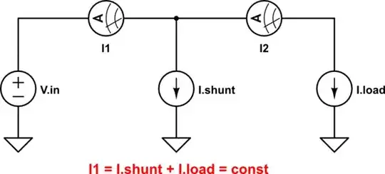
simulate this circuit – Schematic created using CircuitLab
It is still a good old constant current source, just with current sensing not at the load, but at the input, and the current going to ground, not to the load. Otherwise, the high-level structures of those are identical:
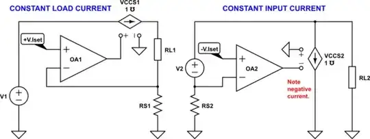
simulate this circuit
At DC, it's just about that simple. A PMOS has conveniently negative voltage-current response: just what we need!
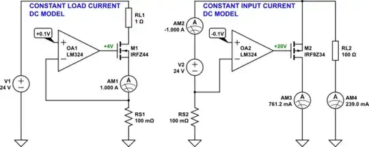
simulate this circuit
To get something practical, we need AC compensation of course. And LM324 is probably a bit too slow for the job - we'll fix that soon.
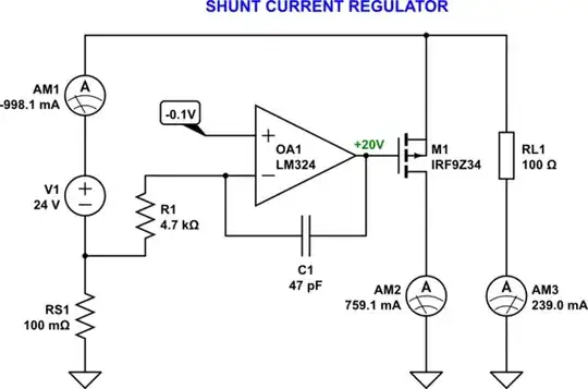
simulate this circuit
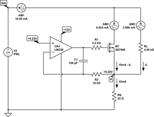
And we'd probably want it to work without the need for a negative supply. Since the current sensing will be on the high side, we need to use an op-amp with common mode voltage extending to positive supply. TL08x is fit for the job, whereas LM324 has common mode range extending to ground instead of VCC, and is much slower.
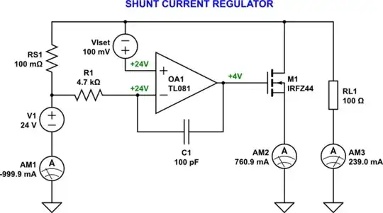
simulate this circuit
Next two bits of impracticality are:
- The current setpoint voltage source is hard to implement.
- Since the input voltage is changing, we'd want to reference everything to the input voltage, so that the op-amp would not need to compensate for that.
R3 sets the current:
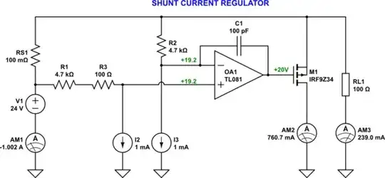
simulate this circuit
Now the problem is relegated to two current sources. Let's simplify further:
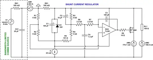
simulate this circuit
R5 sets the current, and C4 should be adjusted for best transient response, in-circuit - due to parasitics, this will be layout-dependent. I1 probably should be LM334-based. R1-R5 are a bridge that configures the op-amp for current regulation.
The key to making this possible with low-cost parts is getting the common mode swings outside of the view of the control loop. The op-amp is powered from a constant 10V, and never "sees" the large voltage swings on the input. The shunt M1 is controlled by a gate-source voltage that's also fixed from the point of view of the control loop.
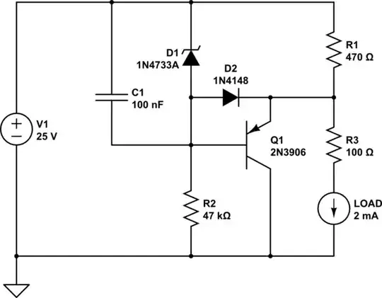
Instead of I1+D1 for 10V generation, we could use a negative voltage three-terminal regulator, like LM79L09:
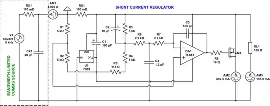
simulate this circuit
Now, if you really want very small currents, then an LM334 will do that job all by itself. Or an op-amp by itself.

simulate this circuit
Or, if you want something somewhat cheaper than LM334, with potential for better transient response, but requiring some adjustments:
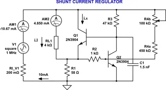
simulate this circuit
Adjustments:
Set current using R1.
Adjust R4b to null the current step when the voltage is changed.
Connect a low-inductance capacitor substitution box in place of C1. Adjust for best response. Measure the capacitor substitution box's impedance using an LCR meter. Reproduce similar impedance using discrete parts (capacitor and potentially resistor).
Q2's Vbe is used as a voltage reference against which the shunt resistor R1 is compared. This circuit has a fairly fast response, so at 800Hz it should be largely transparent.


