1

I just made this circuit that I can't even properly name as it has unique features. My question is if there is an easy way to do this.

Required features:

  • Constant current sink 10mA
  • Variable power supply (20-40V). Current must be constant from any input range.
  • Variable output current. If the device in the output sinks 1mA, the input power supply must still source 10mA. I call it a complementary current sink circuit.

The circuit that I simulated works but I think there's a better way.

Simulation circuit: LINK
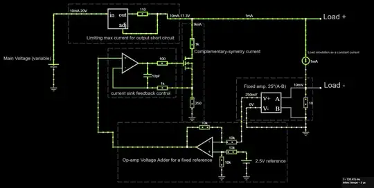
enter image description here

Luis Carlos
  • 312
  • 2
  • 9
  • Where's the 10 mA sink circuit? – Andy aka Oct 12 '22 at 10:30
  • Everything, except the limiting current LDO circuit. After the LDO, the circuit splits in two where the sum of the two currents are always 10mA – Luis Carlos Oct 12 '22 at 10:37
  • Is this just a "differential" current "source"? – Antonio51 Oct 12 '22 at 11:19
  • What is this circuit trying to accomplish? I think the entirety of it may be an XY problem. Why do you think it is important to always draw 10 mA from the constant-current configured linear regulator? – Oskar Skog Oct 12 '22 at 13:00
  • 1
    It’s a requirement for the end case circuit. The load circuit can’t cause any type of current-noise from the power supply. Current must be always constant no matter what the load circuit is doing. – Luis Carlos Oct 12 '22 at 18:36
  • Why not regulate the sum of the two currents in place of the "complementary" one? – Antonio51 Oct 13 '22 at 12:28
  • That was exactly my first circuit but it have undesirable effects: the regulator would need to be at limiting mode all the time and it would consume all the available power by dropping the voltage when the variable load decreases the voltage. – Luis Carlos Oct 13 '22 at 22:44

0 Answers0