0

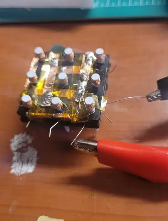
I'm trying to create a grid of electromagnets to move around some iron filings on a piece of paper. I made a prototype with a 3x3 grid made of some nails and enamaled wire, and but I've found that whenever I turn on one magnet, the others all seem to activate as well.

I'm fairly certain the wiring is correct, I can't think of a way the PSU would be supplying current to all nine magnets. I'm guessing the magnetic field is preferentially passing through the nails instead of just the air.

Is that the case? And is there a way I can combat that?

I had some ferromagnetic tape that I tried placing between the nails but I didn't have much luck, I've also tried a non magnetic core but the magnet was too weak to be useful.
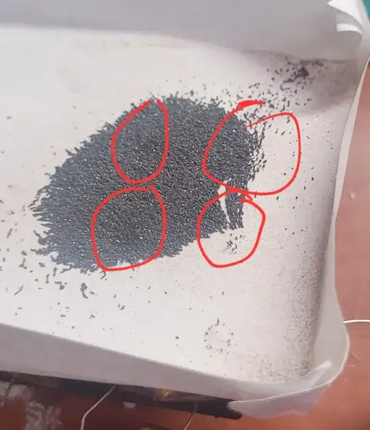
tough to see, but more than one point where the filings are being attracted

prototype

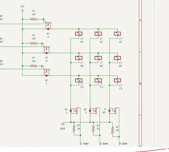
Circuit Diagram

Transistor
  • 175,532
  • 13
  • 190
  • 404
Cccel
  • 1
  • 1
  • 1
    Your lower diagram seems to show all electromagnets connected in a matric hence, without steering diodes they will all be connected. – Andy aka Dec 04 '22 at 22:25
  • The prototype's a mess, but I added in the schematic to clarify how it's wired. – Cccel Dec 04 '22 at 22:43
  • 1
    @Cccel Just a quick question. Something that immediately comes to my own eye, and I'd like to see if you feel similarly, is that the shortest magnetic path (for the lines suddenly finding themselves transitioning from metal to air at either end of a nail) would be through a nearby nail. There would be less air pathway using that route and thereby less recluctance. Just curious if you see that as well. – jonk Dec 04 '22 at 22:51
  • Yes, nails have lower "reluctance" than air, so magnetic fields will preferentially pass through them. –  Dec 04 '22 at 22:55
  • 2
    Aren't the body diodes of all the low-side transistors going to just conduct whether their gates are high or low? Seems like the low-side mosfets are not going to work correctly as-is. Also, I am not clear on how the magnetic circuit works. The flux from one magnet may find it easier to travel back to its origin through one of the other cores, even if the core is not being deliberately energized. – user57037 Dec 04 '22 at 22:58
  • 2
    In the future, if you post a schematic here, it is helpful if the components have reference designators to facilitate discussion. Just something to remember for next time. Not a big deal. This is an interesting question. – user57037 Dec 04 '22 at 23:00
  • The flux issue could possible be fixed or at least improved by providing a low reluctance path back to the under side. Or maybe you could actively degauss all the unused magnets to keep the flux at zero. – user57037 Dec 04 '22 at 23:02
  • 1
    The GND side FETs seem wrong. Are you sure they are as in the schematic? – Justme Dec 04 '22 at 23:05
  • The lowside Mosfets do seem to be backwards! They are not currently in the prototype, my bad for including them in the schematic for this particular question. – Cccel Dec 04 '22 at 23:08

0 Answers0