Certainly!
Two resistors are needed to limit both upper and lower range. One resistor at the bottom if you just want to limit the lower level.
You won't end up with exactly 0.500 and 4.500 V without adjusting the values to odd ones (out of E12 series), but close enough for your application?
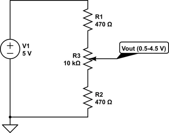
simulate this circuit – Schematic created using CircuitLab
As pointed out by vu2an, the mathematically ideal values for R1 and R2 is 1.25 k\$\Omega\$ for a 10 k\$\Omega\$ pot. Downside is that 1.25 k\$\Omega\$ is not even in E192 series.
As pointed out by charmer, if you need precise 0.5 to 4.5 V range, possibly with 10 % tolerance on your 10 k\$\Omega\$ pot (the elephant in the room), you need an arrangement like this:
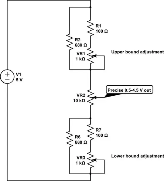
simulate this circuit
VR1 and VR3 are pots in rheostat configuration and R1, R2, R6 and R7 are to desensitize VR1 and VR2 adjustments to give you more fine control. Probably way overkill. Feel free to adjust values to give you more room for adjustment (remove R1, R2, R6 and R7 completely) or finer control.
Happy poting!
