8

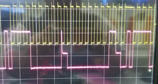
I am trying to communicate from master to slave using I2C communication. But during the 9th clock cycle, the slave is trying to pull high to low but it can only pull it down to half the voltage (3.3 V to 1.3 V).

screenshot of I2C signals

I changed the pull-up from 10 kΩ to 33 kΩ then 4.7 kΩ but without getting an improvement in the result. I also changed the slave IC but no improvement. Is there any way to solve the problem?

My pull-up voltage was 3.3 V. Also I tried sending the I2C signal by toggling GPIO pin, but same problem happening here also.

SamGibson
  • 17,870
  • 5
  • 40
  • 59
spani
  • 83
  • 5

3 Answers3

17

It looks like your data pin is a push pull output which is wrong. Make sure both the data and clock pins are open-drain outputs as requires by I2C protocol.

Justme
  • 147,557
  • 4
  • 113
  • 291
  • 5
    That is consistent with the sharp rising edges, no hint of an RC curve. – Technophile Mar 27 '22 at 05:20
  • 5
    The most revealing part is not the missing shark-fin like curve, because for slow frequencies with strong pull-ups, the RC curve could be relatively square-wavish on a scope with slow time scale. But the revealing part is that both falling and rising edge have the undershoot and overshoot spikes clearly visible, and the overshoot would not be there if it was a slow RC waveform. – Justme Mar 27 '22 at 15:26
  • 1
    Thanks, now it is working after making the pins as open-drain. – spani Mar 28 '22 at 09:17
6

I will take a SWAG and assuming you are talking to a microprocessor with that pin programed as an output.You need to program it as a pull up or open collector depending on the micro.

Gil
  • 5,113
  • 2
  • 13
  • 14
1

As per the other answers, the master is driving the line high. Nothing should drive the line high in I2C.

This answer is for the case of bit-banging using GPIO.

To implement and open-drain type output required, you should only drive the line low, and let it float high by configuring it as high-Z or input. (Also, when you let it float, there will be a requirement to read it in case the slave drives it low).

The following pseudo-code illustrates an open-drain type output for bit-banging

void init_pin_for_i2c(int pin) {
    // Initialise for high impedance (for idle)
    gpio_set_mode(pin, HIGH_Z);
// Now set the output to zero, this is the only value we will ever drive onto the bus
// It will only be driven to the bus when we switch the mode to OUTPUT
gpio_write_value(pin, 0);

}

void write_pin_for_i2c(int pin, int val) { if (val == 1) { // To "write" a 1 to the bus, let the pin float high gpio_set_mode(pin, HIGH_Z); } else { // Enable the output to assert zero on the bus gpio_set_mode(pin, OUTPUT); }

Note that for HIGH_Z you may need to use mode INPUT, depending on your API and your MCU.
Rodney
  • 342
  • 1
  • 6
  • 3
    Even if the MCU has I2C hardware peripheral, it does not mean it automatically configures the IO pin stage correctly for you, and many MCUs don't. Not MCUs are like Arduinos or AVRs, each MCU has their own way how things are done. – Justme Mar 27 '22 at 15:20
  • 2
    STM32. You can configure IO pin mode irrespectively of the routed peripheral, GPIO or some other peripheral. So it does not force that UART pin is a push-pull, you can configure UART pin to be open-drain, which is handy if UART happens to be configured for single-pin half-duplex. So when connecting I2C peripheral, the pin mode and routing must be done accordingly. – Justme Mar 28 '22 at 14:55
  • 1
    @Justme I think the answer is still relevant for people who search this because some will be bit-banging. So I re-worded it a bit to make that clear that this is just for that case, and removed the assumption that the OP it bit-banging. – Rodney Mar 28 '22 at 15:10