2

I'm building a EDM machine for removing broken metal-working taps. I'm using the following circuit, but having issues with the IGBT transistor

enter image description here

R1 = 2Ohm resistor
C1 & C2 = 1000uf 100V capacitor
IGBT = IRG4PC40KDPbF IGBT
P = from the positive side of 5V 1A power supply

According to the datasheet (page 2), the Gate Threshold Voltage is 3 (min) to 6 (max) volts. When I apply 5V to P, I would expect the resistance across the collector & emitter to drop low, but it doesn't.

I have tried also connecting the negative from the 5V power supply to the IGBT emitter, but with no change.

Any thoughts?

  • 3
    If by "open" you mean "starts to conduct electricity", as in the valve & plumbing analogy -- try to purge that from your vocabulary. When an electronics engineer says that a transistor is "open" they're using the switch analogy -- "open" means "open circuit" means "off"; "closed" means "closed circuit" means "on". It's much less ambiguous to use "on" and "off". – TimWescott Oct 03 '21 at 14:25
  • Vgth is the MINIMUM gate voltage at which conduction BEGINS 6v is the worst case minimum | Vge_max is +/- 20v (page ) | See fig 3 for needed gate voltage. About 10 V looks good. – Russell McMahon Oct 05 '21 at 12:49

3 Answers3

5

The IGBT may have a Vth of 3-6V, but it'll need 10-15V to properly turn on to its minimum on-state resistance. The gate threshold voltage is determined under this condition:

enter image description here

Take a look at the Vge vs Ic graph in the datasheet

enter image description here

From the graph, at Tj = 25, you can see that the IGBT needs close to 6V for an amp of current to start flowing through it.

Presonally, I would use 15V to turn it on.

Prathik Prashanth
  • 1,016
  • 4
  • 17
  • Thank you Prathik. When I tried replacing P with a 12V 1A supply earlier, the IGBT blew (or rather, all pins had connectivity to all other pins).

    To test, would I be safe applying 12V to G, then putting a multi-meter across C and E to measure resistance?

    – Derek Bartram Oct 03 '21 at 12:32
  • @DerekBartram How much does the SOAR for the IGBT cover and how fast do you switch it? – winny Oct 03 '21 at 12:52
  • Measuring the on-state resistance is not as simple as putting a multimeter across C and E. Also, a Vge of 12V cannot blow your IGBT up. – Prathik Prashanth Oct 03 '21 at 13:01
  • Thanks Winny & Prathik.

    I'm not sure what SOAR is. I'm currently switching on and off manually; later will be higher frequency controlled by microcontroller, but not there yet.

    @PrathikPrashanth So... I tried removing the capacitors, then putting my multimeter across ELECTRODE-WORKPIECE in current mode. Turning on, gave 9-10A current, without any application of power at P. IGBT now shows as short across all pins (which I believe means dead)

    – Derek Bartram Oct 03 '21 at 13:28
  • 1
    You cannot switch an IGBT "manually" if it is connecting a charged capacitor directly to a workpiece. All switches "bounce" and are way too slow. The IGBT must be "fully on" or "fully off" - no in-between state - else it absorbs all that capacitor energy, and fuses into a solid hunk. – rdtsc Oct 03 '21 at 14:16
  • @rdtsc Why not (trying to understand, not saying you're wrong)?

    From a new circuit/components, then the IGBT would be closed and C2 would charge. On application of 15V to P, the IGBT should open causing a single discharge through the workpiece (or ammeter in my later; current would change from 0 to power supply limit)?

    – Derek Bartram Oct 03 '21 at 14:39
  • I think using "conducting" and "non-conducting" might remove ambiguity in your question and comments. – Transistor Oct 03 '21 at 14:44
  • Please show exactly how you are switching the gate with a schematic. +1 on what @rdtsc said, any contact bounce and your IGBT is probably done for due to it ending up in linear region and outside of its SOAR (safe operatting area). – winny Oct 04 '21 at 09:08
  • Thanks all, much appreciated.

    In my most recent test I did. +60V ---> ammeter ---> IGBT (C-E) ----> 0V Nothing connected to IGBT-G. Chip fried.

    In prior tests which I was attempting to get to the IGBT to conduct across C-E, I had connected G directly to a powered 12V supply (which read as 15V) using a piece of wire only - no switches, purely a single wire.

    – Derek Bartram Oct 04 '21 at 10:52
  • From further research, it appears in my desired case using a microcontroller giving PWM, I'm going to be needing to look at a driver chip to provide the required current requirements. However.... this doesn't solve the chip dying with nothing more than 60V 9A connected across it (with 2ohm resistor in series to limit current) – Derek Bartram Oct 04 '21 at 10:54
1

"Threshold" in MOSFETs and IGBTs is a trap for newbies. It's a deep technical term that has to do with the shape of the current vs. gate voltage curve, but isn't something that you can just measure. Probably the simplest way to put it is it's the gate voltage where the device just barely starts to conduct -- but even that is kinda-sorta wrong.

For switching applications, you don't care about the threshold voltage. You care about the rated gate-emitter voltage to turn the device fully on, the rated gate-emitter voltage to turn the device fully off, and getting the thing turned on and off fast enough so it isn't damaged (as mentioned above), and for big IGBTs, not turning it on so fast it goes into CMOS lockup.

As mentioned, that prescribed gate-emitter voltage is probably around 10 to 20V, depending on the IGBT you're using.

TimWescott
  • 46,144
  • 1
  • 42
  • 107
1

If your load resistance is below 0.75 ohm (with safety margin and at room temperatures,) a pulsed inrush current from capacitor C2 could surpass the datasheet specification for maximum pulsed current of 84A.

That IGBT adds 0.17 ohm for a voltage drop of 1.7V for 10A measured to load resistance and on about 4V for 84A that calculates to only 0.012 Ohm. Minimum acceptable load resistance would be around 0.75 ohm.

Below that resistance fully switching on possibly destroys this IGBT in this circuit, if it is conducting at lowest resistance, because of (inrush) over-current. Within 0.4-0.5 milliseconds that electrolytic capacitor C2 will discharge to half of its initial (60V) voltage on a load resistance at about 0.75 ohm and it will need these 1/2000 second for reducing its initial maximum current of around 80A to about (its half) 40A also. Load resistances below about 0.75 ohm will let the initial current start at values above 80-84A. Suitable guess for the endurance of the over-current (for to avoid) is http://hyperphysics.phy-astr.gsu.edu/hbase/electric/capdis.html#c2 .

For breakdown voltage of an arc within air
(or other gases: \$H_2\$ (A=38.3, B=1041), \$He\$(A=22.5, B=255), \$Ar\$(A=102.0, B=1763), \$CO_2\$(A=150.0, B=3495) for A,B=[\$(kPa*cm)^-¹\$] ),
Paschen's Law online calculator (e.g. \$p=\$100000Pa, \$d=\$0.004mm, \$\gamma_s,_e=\$~0.5-2.0 (or values diagram) ) might provide further insight into possible minimum voltage values, that, from theory, hardly undercut ~30-35V for metals and air, hydrogen, argon (exceptions: \$He\$ and minor effective \$CO_2\$ atmosphere) (Sidenote: While knowing, that in reality even on car battery's low, nominal 12V sparks can be visible between positive wiring and vehicle shell).

For researching IGBTs, for example Infineon IRGP4069 and understanding parameters during switching on

  1. Discrete IGBT Simulator, for example: 100V, 80A, 10Hz
  2. datasheet IRGP4069, page 9
  3. CircuitLab Simulation

schematic

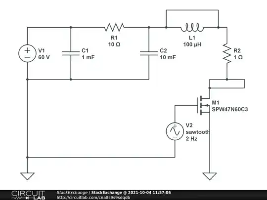
simulate this circuit – Schematic created using CircuitLab

JRE
  • 71,321
  • 10
  • 107
  • 188
beyondtime
  • 186
  • 8
  • Aha, yes, that would make sense... I think that's what's killing it! I'll get another couple ordered, and put a current limiting 1 ohm resistor in place; hopefully that won't affect the spark generation too much. Thank you; I'll report back. – Derek Bartram Oct 03 '21 at 14:55
  • 1
    "The rapid transition from a non-conducting to a conductive state produces a brief emission of light and a sharp crack or snapping sound. A spark is created when the applied electric field exceeds the dielectric breakdown strength of the intervening medium. For air, the breakdown strength is about 30 kV/cm at sea level." Electric_spark on Wikipedia, voltage drop on 1 (and wiring) ohm resistor for 40A would be 40V (~ milliseconds). You might need a different inrush current limiter (suitable gate voltage) or IGBT's accepting higher current pulses or starting with <60VDC (without add. resistor). – beyondtime Oct 03 '21 at 16:26
  • Thanks for the help beyondtime, it's greatly appreciated. Am I looking for something like https://www.farnell.com/datasheets/1911584.pdf (300A for 1ms), or https://www.onsemi.com/pdf/datasheet/hgt1s12n60a4ds-d.pdf (which suggests a larger short circuit time/current, page 3)? – Derek Bartram Oct 04 '21 at 10:46
  • 1
    What found out of interest, distance is down to 0.16mils (.004-.5mm), what translates to min ~50V-1.95kV for air between metallic electrodes and work piece surface. Far below 60V could be probably difficult for bridging air or even argon(?) gap, depending on all included materials (carbon layer?) and/or inert atmosphere around electrodes. (Wikipedia for edm m. and Paschen's law might be useful). With circuit simulation done before, it might be of help including a low winding coil before work piece, made of strong copper wire. Do you still get sparks with 2 ohm load resistance? – beyondtime Oct 05 '21 at 07:29
  • 1
    Probably useful with IGBT's also is avoid free floating gate voltages by pull-down resistor from gate to ground for to switch-off without input signal to gate? (Probably, your ammeter doesn't show fast transient current spikes during startup time, but more likely sums current values to average for some 1/10th of a second.) Hopefully you don't exceed the IGBT's temperature limits with enduring 60V 9A requiring ~15W power dissipation/heat sink path (at least, for this 9A)? – beyondtime Oct 05 '21 at 07:30
  • pretty educational: https://www.youtube.com/results?search_query=edm+machine &thx for interest – beyondtime Oct 05 '21 at 08:56