0

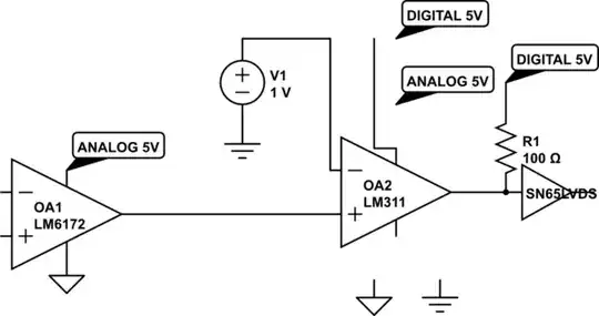
My schematic looks like this:

schematic

simulate this circuit – Schematic created using CircuitLab

How should i connect ground and power supply to comparator? I have some signal which i want to convert to LVDS. My output stage from analog is based on LM6172. I convert amplitude to pulse width via comparator LM311 which then goes to LVDS driver. Comparator has both neagtive and positive power supply and GND port. I usually separate analog and digital grounds and power supply (with some ferrite beads i.e) but i dont know really how to do this here. Second input of comparator is DAC which is connected to digital GND. So should I connect my comparator to digital or analog power supply and ground? I thought about using optocoupler but i dont have much space on board for that.

kamj
  • 23
  • 4
  • Don't share digital current on analog gnd traces. Why use a slow LM311 ? – Tony Stewart EE75 Sep 06 '21 at 09:33
  • Why is LVDS driver output shorted? What do you transmit LVDS to? Is that remote circuit using a differential input? Is the remote circuit using a single ended input that may cause problems if you interconnect grounds? Too many things are unclear. – Andy aka Sep 06 '21 at 09:36
  • None of this schematic is logical -1 – Tony Stewart EE75 Sep 06 '21 at 09:37
  • @TonyStewartEE75 LM311 i think is good in this case of speed and also has emiter output. Schematic is just a visualization what ground is connected where – kamj Sep 06 '21 at 10:07
  • @Andyaka LVDS isnt shorted I just want to show which ground is connected to LVDS. I will change it – kamj Sep 06 '21 at 10:07
  • Using a very slow comparator to drive a fast one makes no sense. What are your trying to transfer and how far? – Tony Stewart EE75 Sep 06 '21 at 10:56
  • @TonyStewartEE75 Actually I want to send signal differentially because of possible noises. Speed is not the key. – kamj Sep 06 '21 at 11:27
  • Please clarify your specific problem or provide additional details to highlight exactly what you need. As it's currently written, it's hard to tell exactly what you're asking. – Community Sep 06 '21 at 12:49

1 Answers1

3

You have a valid concern that every EE meets it during the circuit design.

It is often not possible to isolate analog and digital domain. Many microprocessors include ADC, DAC, programmable gain OPA, reference voltage generator, and comparators, along with the processor core in a device.

A circuit ground has two important meanings. One is the "return path" of current. Another is "reference point" of signals, ie. voltage. Unless these two properties interfere, analog and digital can share a ground much easier. Meantime, bright sides is that only two have to be resolved.

Right to the answer:

  1. Bypass (cap) the Vdd & Vss of the comparator to the AGND, as the same as the OPA. The reason is that comparator input, thus the OPA output, is referencing on AGND.

  2. Use as large pull-up as possible, to the comparator output, not 100 ohm, and pull it up to analog Vdd. And then, buffer that output on digital side. The reason is that the comparator passes the current through the pull-up to the connected analog ground. Active output comparators or an OPA can be used as well.

  3. Connect the "ground of DAC", "AGND of the comparator", and the Digital Ground. If power ground was shared (common) to analog and digital, then place the power ground where DGND and AGND meets. Thus the grounding point becomes the center of the "star connection".

  4. Avoid "ground loop" anywhere. If that is unavoidable, make the loop as small as possible.

jay
  • 3,841
  • 9
  • 24